ZSim and ZFit as learning tools. Part I – Acidic corrosion
Latest updated: June 2, 2023This is the first in a series of articles about ZSim and ZFit as learning tools.
Summary:
- Part I – Acidic corrosion
- Part II – Why circle fitting is wrong?
- Part III – How to detect an inductive behaviour at low frequencies?
- Part IV – The effect of high frequency inductance
- Part V – How to choose the proper equivalent circuit?
- Part VI – Equivalent circuits distinguishability
- Part VII – Equivalent circuits identifiability
ZSim and ZFit – important modeling and simulation tools for EIS. How they work…
ZSim is the powerful Electrochemical Impedance Spectroscopy (EIS) simulation tool available in EC-Lab®, the control and analysis software for BioLogic potentiostats. ZSim is a great educational tool to help users understand how impedance graphs can be used to access the intricacies of the electrochemical process occurring at the interface. These simulations allow us to understand EIS measurements without even using a potentiostat.
ZFit (part of EC-Lab®) is an important EIS fitting tool that is used to interpret EIS data using electrical equivalent circuit modeling. An introduction to ZFit together with guidelines demonstrating how to choose the best equivalent circuits are given in the BioLogic application note 14 [1].
In this article, Zsim simulates an impedance graph showing a low-frequency inductive loop. A given equivalent circuit is used to simulate the data, and ZFit fits the data with another equivalent circuit, showing the indistinguishability of R/(L+R) and R+C/R circuits.
Electrical equivalent circuits with low-frequency inductive arcs
The impedance diagrams of electrochemical reactions with two successive steps, for example, the oxidation reaction of iron in an acidic medium [2], or the Volmer-Heyrovský proton reduction reaction, present a low-frequency capacitive or inductive arc, depending on the electrode potential. For the Volmer-Heyrovský reaction, the diagrams are constituted successively, as the electrode potential decreases, of a low-frequency inductive arc together with a high-frequency capacitive arc (Fig. 1a), a capacitive arc alone (Fig. 1b), and finally two capacitive arcs for the most negative potential (Fig. 1c) [3].

Figure 1: Steady-state $i_\text f\;vs.\,E$ curve and impedance
diagrams for the Volmer-Heyrovský reaction. (Animation).
Inductive impedance with L and R
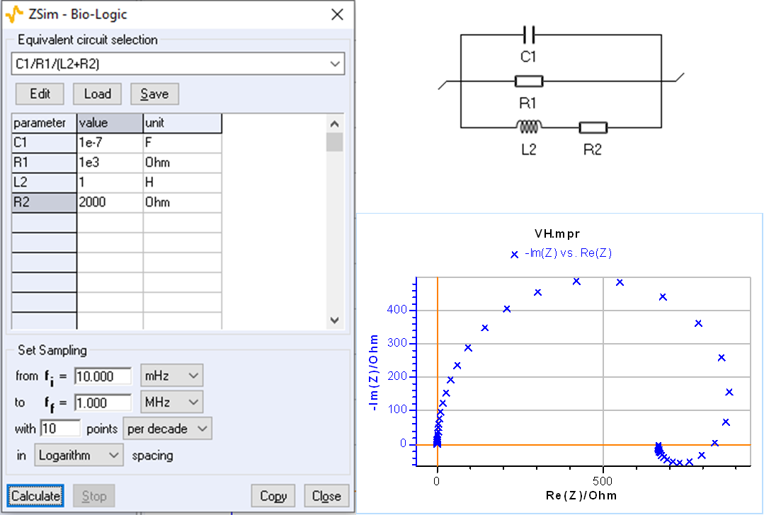
Using ZSim, the impedance simulation tool available in EC-Lab®, it is easy to plot impedance diagrams with a low-frequency inductive arc for the C1/R1/(R2+L2) circuit as it is shown in Fig. 2.

Figure 2: C1/R1/(R2+L2) circuit: impedance diagram with a low-frequency inductive arc.
Inductive impedance with R and C
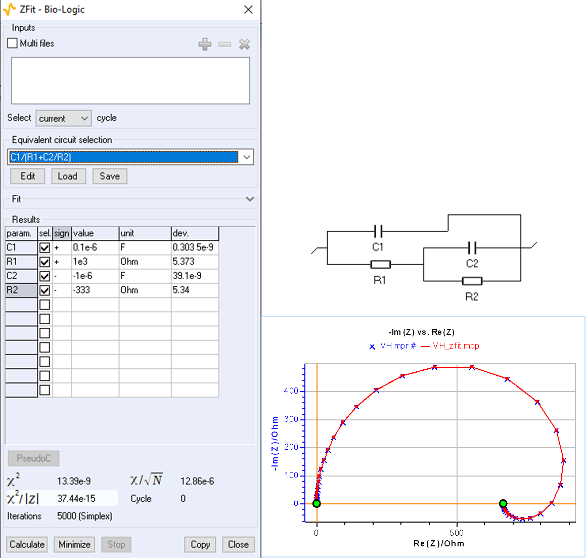
An impedance diagram with a low-frequency inductive arc can also be obtained for the circuit C1/(R1+C2/R2) with negative values of R2 and C2, as shown by the parameter’s value in Fig. 3. A good fit is easily obtained by forcing R2 and C2 to be negative by choosing the minus sign in the “sign” box of the ZFit window
At the beginning of the fitting process, the software looks for initial values randomly, this is why several attempts may be needed initially for the process to succeed.
The C1/R1/(R2+L2) and C1/(R1+C2/R2) circuits can therefore be used interchangeably to interpret a low-frequency inductive impedance arc. These two circuits are termed indistinguishable [4].

Figure 3: Fit with ZFit of the impedance shown in Fig. 2 using the C1/(R1+C2/R2) circuit.
Capacitive impedance with R and C
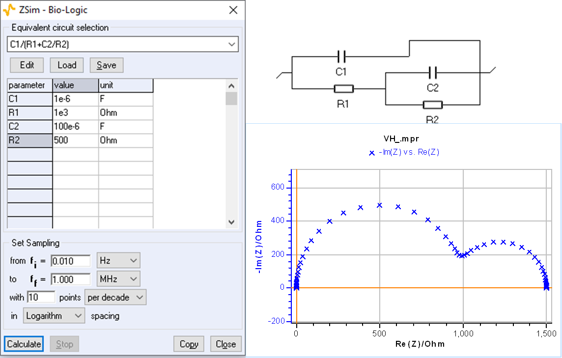
Using ZSim, it is easy to plot impedance diagrams with a low-frequency capacitive arc for the C1/(R1+C2/R2) as shown in Fig. 4.

Capacitive impedance with R and L
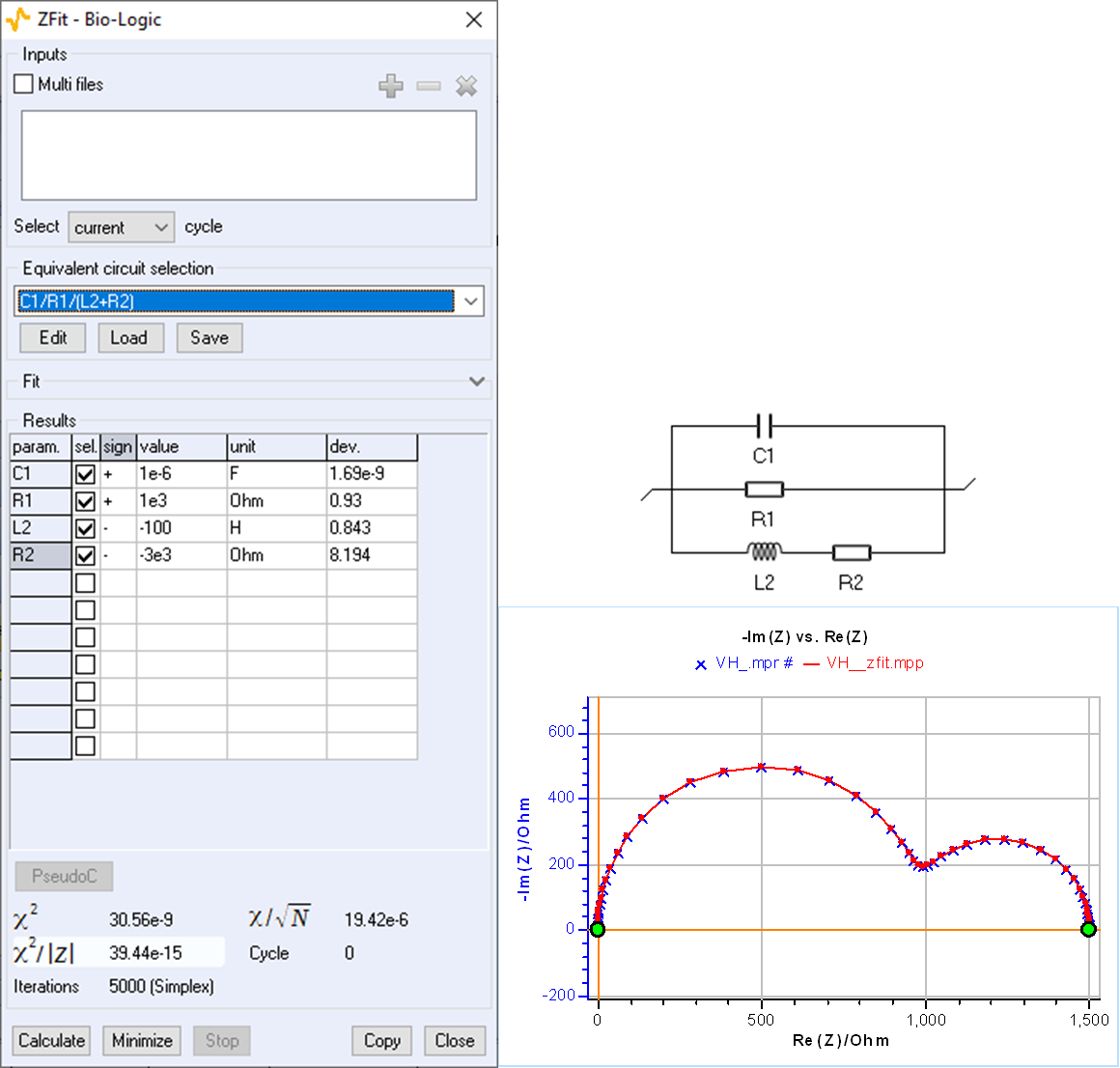
An impedance diagram with a low-frequency capacitive arc can also be obtained for the circuit C1/R1/(R2+L2) with negative values of R2 and L2, as shown by the values of the fit parameters in Fig. 5. A good fit can be obtained by forcing R2 and L2 to be negative.

Figure 5: Fit with ZFit of the impedance shown in Fig. 4 using the C1/R1/(R2+L2) circuit.
Now you know almost everything about low-frequency inductance
The two different circuits C1/R1/(R2+L2) and C1/(R1+C2/R2) can be used interchangeably to exploit the impedance diagrams of electrochemical reactions with two successive steps, including, for example, a Volmer-Heyrovský mechanism. Using ZSim and ZFit facilitates the selection and the choice of equivalent electrical circuits. ZFit allows users to set the sign of the parameters when performing the data fit. The negative sign of the adsorption resistance and capacitance is described in more detail in [6].
Figure 6 below summarizes the various findings and results of this topic. Please note that the most common situation occurs when the system is not polarized, ie natural corrosion in an acidic environment.

Figure 6 : Figure 1: Steady-state $i_\text f\;vs.\,E$ curve and impedance diagrams for the
Volmer-Heyrovský reaction with the corresponding electrical equivalent circuits (Animation).
[1] Application Note 14 “ZFit and equivalent electrical circuits” https://www.biologic.net/wp-content/uploads/2019/08/battery-eis-equivalent-circuit_electrochemistry-an14.pdf
[2] I. Epelboin and M. Keddam. Kinetics of formation of primary and secondary passivity in sulphuric aqueous media. Electrochim. Acta, 17(2):177-186, 1972.
[3] J.-P. Diard, P. Landaud, B. Le Gorrec, and C. Montella. Calculation, simulation and interpretation of electrochemical impedance. Part II. Interpretation of Volmer-Heyrovský impedance diagrams. J. Electroanal. Chem., 255:1-20, 1988.
[4] F. Berthier, J.-P. Diard, and C. Montella. Distinguishability of equivalent circuits containing CPEs. I. Theoretical part. J. Electroanal. Chem., 510:1-11, 2001.
[5] Application Note 42 “The modified inductance element La” https://www.biologic.net/wp-content/uploads/2019/08/battery-eis-modified-inductance-element_electrochemsitry-an42.pdf
[6] J.-P. Diard, B. Le Gorrec, C. Montella, Cinétique électrochimique, Hermann, Paris, 1996, p. 296
Related products
Related accessories