

ZSim and ZFit as learning tools. Part V – How to choose the proper equivalent circuit?
Latest updated: November 18, 2024This is the fifth in a series of articles about ZSim and ZFit as learning tools.
Summary:
- Part I – Acidic corrosion
- Part II – Why circle fitting is wrong?
- Part III – How to detect an inductive behaviour at low frequencies?
- Part IV – The effect of high frequency inductance
- Part V – How to choose the proper equivalent circuit?
- Part VI – Equivalent circuits distinguishability
- Part VII – Equivalent circuits identifiability
The usual procedure to interpret and analyze impedance data is to consider that the system under study is equivalent to an electrical circuit, which is composed of the proper combination of electrical elements: resistors R, capacitors C, and an inductor L connected in parallel and/or in series. As the system under study is electrochemical, sometimes the list of electrical elements is not sufficient to properly model the processes at stake in the reaction.
In this article, we want to highlight certain aspects of equivalent circuit modelling, which hopefully can sharpen your expertise of EIS fitting and guide you in your choice for the most appropriate equivalent circuit. We want to specifically address the inductance element because it is less known than resistance and capacitance and maybe overlooked by electrochemists.
We will then discuss the topic of non-distinguishability. Sometimes, two or three equivalent circuits can be equivocally used to fit your data. In this case you may ask yourself “How do I decide which one to choose?” and by the end of this article you will have a better understanding on how to approach this question. Of course, some of your questions will be left unanswered, if this is the case do not hesitate to contact us.
Inductance
High frequency inductance
As a reminder, the impedance of an inductor with an inductance L is :
$$Z_\text L = Lj\omega \tag{1}$$
With $\omega$ the angular frequency in $\text{rad s}^{-1}$, the inductance, $L$, in $\text H$ and $j$ the imaginary number such as $j^2=-1$.
The impedance of an inductor is a pure positive imaginary number so in the Nyquist representation of the electrochemists $(-\text{Im}\,Z\,vs. \text{Re}\,Z)$ an inductance corresponds to an impedance that is below the real axis.
For low impedance systems, inductive behavior is observed at high frequencies, in this case it is related to a magnetic coupling effect [1]. If this happens it is not recommended to cut the data below the real axis and ignore the inductance, as it actually affects the rest of the graph and it is recommended to simply add the element L to your equivalent circuit. More details can be found in the article : “ZSim and ZFit as learning tools. IV. The effect of high frequency inductance.”
Low frequency inductance
Inductive behavior can also occur at low frequencies. It is sometimes necessary to use a Bode representation instead of a Nyquist representation in order to be able to detect such inductive behavior, described in more details in the article: “ZSim and ZFit as learning tools. Part III How to detect an inductive behaviour at low frequencies”.
Such inductive behavior in electrochemistry, and more precisely in corrosion is involved in acidic corrosion of metals, and is associated with the Volmer-Heyrovský reaction, which is a two-step reduction of protons into dihydrogen. As explained in more details in the article: “ZSim and ZFit as learning tools. Part I acidic corrosion”, the impedance depends on the applied potential and the impedance graph can look very different from one voltage to another.
However, at corrosion potential the Volmer-Heyrovský reaction can be modelled either by an L+R equivalent circuit or a C+R equivalent circuit, but with negative values. These two circuits are non-distinguishable, as they lead to the same impedance graphs, of course for different parameters values. It’s up to you to choose the equivalent circuit you are the most comfortable with!
Non-distinguishable circuits: which one should I choose to fit my data ?
For more details on non-distinguishable circuits, please take a look at the article:“ZSim and ZFit as learning tools. Part VI. Equivalent circuits distinguishability”. This article describes two non-distinguishable circuits: the Voigt and the ladder circuits.
Below we show the consequences of the non-distinguishability on results obtained on Test box #3.3
The problem
Impedance diagrams measured on Test Box #3.3 for potentials varying from 0.4 to 0.6 V are presented in Fig. 1. The graphs are made of two semi-circles and can correspond to the equivalent electrical circuits C1/R2+C2/R2 (Voigt circuit) or C1/(R1+C2/R2) (ladder circuit) [2].

Figure 1: Impedance diagrams measured on the Test Box #3.3 for potentials varying from 0.4 to 0.6 V.
Let us assume that the Test Box #3.3 is made of the C1/R1+C2/R2 equivalent circuit with a value of the resistance R2 which varies with the potential.
Using ZFit, it is possible to automatically fit the impedance graphs shown in Figure 1 [3]. The fits are performed successively by taking the values obtained for the previous impedance graph as initial values of the parameters, except of course for the first graph where a random step is necessary.


Figure 2 : Fit of the impedance shown in Fig. 1 using the C1/R1+C2/2 Voigt circuit and change of resistances R1 and R2 with the potential.
The result of the fit is shown in Fig. 2 for the two resistors of the circuit. Hereafter, for the sake of simplicity, only the values of R1 and R2 will be presented, equivalent results being obtained for C1 and C2.
The circuits C1/R1+C2/R2 and C1/(R1+C2/R2) being indistinguishable, the circuit C1/(R1+C2/R2) can also be used to fit the impedance graphs of Fig. 1. The result is shown in Fig. 3

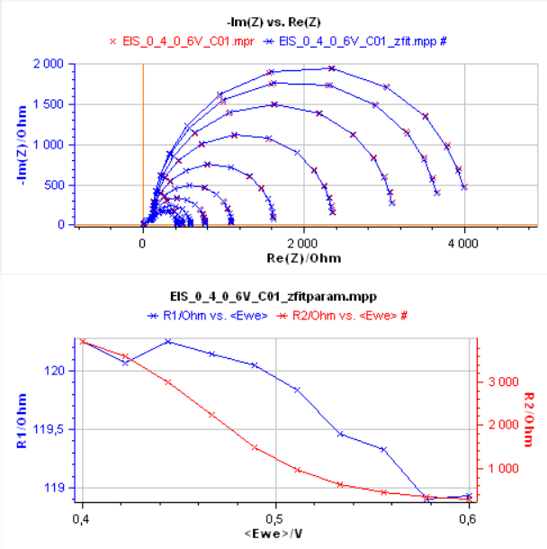
Figure 3 : Results from the successive fittings of impedance graphs from Fig. 1 with circuit C1/(R1+C2/R2).
The change of R1 and R2 with electrode potential are similar but the values are different. Both circuits can therefore be used and there is a priori no argument for choosing one circuit over the other.
What should I do ?
Choose the circuit for which all elements are identifiable
Some equivalent circuits, because of the structure of their impedance, contain elements that are not identifiable. We can take, for example, the Voigt circuit with two R/Cs (R1/C1+R2/C2). Fitting the data, like in Fig. 2 could lead to different results: the values of the R1 parameter could be those of the R2 parameter, the values of the C1 parameter could be those of the C2 parameter and vice versa.
This is not the case for the ladder circuit, any fitting of the same data will lead to the same values for all parameters. Each parameter is identifiable.
You can read more details on this subject in the following article:“ZSim and ZFit as learning tools. VII. Equivalent circuits identifiability”.
Choose the equivalent circuit whose structure matches the physical system under investigation
When the system being studied consists of a three-electrode assembly with a working electrode, the ladder electrical circuit (Figure 3) is selected first. This is because the ladder circuit matches the Faradaic impedance structure for an electrochemical reaction where R1 = Rct with Rct the charge transfer resistance, and C1 = Cdl with Cdl the interfacial double layer capacitance [4]. The electrical circuit is, for example, equivalent to a two-step electron transfer reaction, such as the Volmer-Heyrovský reaction of dihydrogen evolution mentioned above [5]. The evolution of Rct with electrode potential can then be used to determine the kinetic parameters of the reaction [6].
When the system being studied is an electrochemical system with two electrodes (e.g. batteries, capacitors, fuel cells, electrolyzer, etc.), the Voigt electric circuit (Figure 2) is preferred because it shows two R/Cs, where one can be assigned to one of the two electrodes of the system and the second to the other electrode.
Any prior knowledge about the system guides you to the most appropriate choice between electrical equivalent circuits. The more you know about the system, the better.
Conclusions
In this introductory article, we presented a few elements to help you chose the proper equivalent circuit when fitting impedance data. We examined the inductor element L, related to either high frequency artifacts or low frequency adsorption mechanisms. In the case of low frequency adsorption, the impedance data can be fitted with two non-distinguishable circuits. If this is the case for you, we outlined two arguments that you can use to know which equivalent circuit is the best choice for your system.
[1] Application Note 5: Precautions for good impedance measurements
[2] Application Note 49: Linear vs. non-linear systems in impedance measurements
[3] Application Note 45: ZFit and multiple impedance diagram fitting
[4] Application Note 14: ZFit and equivalent electrical circuit (EIS Equivalent circuit)
[5] Learning center Article: ZSim and ZFit as learning tools. Part I acidic corrosion
[6] J.-P. Diard, P. Landaud, B. Le Gorrec, C. Montella, Calculation, Simulation and Interpretation of Electrochemical Impedances II. Interpretation of Volmer-Heyrovsky impedance diagrams. J. Electroanal. Chem. 255 (1988) 1-20. https://doi.org/10.1016/0022-0728(88)80001-9


