

ZSim and ZFit as learning tools. Part VII – Equivalent circuits identifiability
Latest updated: November 18, 2024This is the seventh in a series of articles about ZSim and ZFit as learning tools.
Summary:
- Part I – Acidic corrosion
- Part II – Why circle fitting is wrong?
- Part III – How to detect an inductive behaviour at low frequencies?
- Part IV – The effect of high frequency inductance
- Part V – How to choose the proper equivalent circuit?
- Part VI – Equivalent circuits distinguishability
- Part VII – Equivalent circuits identifiability
When choosing an equivalent electrical circuit, it is important to evaluate whether different component values can be measured without ambiguity. For example, it is obvious that the individual resistor values $R1$ and $R2$ in the circuit $C1/(R1+R2)$ cannot be determined by impedance measurement, but rather only the sum $R1+R2$ can be determined. But other cases may be less obvious.
Unidentifiable circuit
The C1/R1+C2/R2 Voigt circuit
Voigt circuits consisting of several R/C circuits in series (Fig. 1) are widely used in battery studies [1,2].

Figure 1: C1/R1+C2/R2 Voigt circuit.
The impedance of the C1/R1+C2/R2 Voigt circuit in Fig. 1 is given by:
$$Z_\text V(p)=\frac{{R1}}{1+{C1} {R1}\,p}+\frac{{R2}}{1+{C2} {R2}\,p}, \text{ with } p=\text i \,2 \pi f \tag{1}$$
and its normalized form:
$$ Z(p)=K\,\frac{1+a_1 p+a_2 p^2+\cdots}{1+b_1 p+b_2 p^2+b_3 p^3+\cdots} \tag{2}$$
by:
$$Z_\text V(p)=\frac{({R1}+{R2}) \left(1+\dfrac{({C1}+{C2}) {R1}{R2}\,p}{{R1}+{R2}}\right)}{1+({C1} {R1}+{C2} {R2})\,p+{C1} {C2} {R1} {R2}\,p^2} \tag{3}$$
Relations (1) and (3) are symmetrical with respect to the components R1, R2 and C1, C2. Swapping indices 1 and 2 does not change the relation.
Therefore, the same impedance diagram is obtained for the following two sets of parameter values:
$C1=6 \times10^{-5}\, \text F, \;R1 =150\;\Omega \ ;\ C2=10^{-3}\;\text F,\;R2=325\,\Omega \tag{4}$
and:
$C1=10^{-3}\;\text F, \;R1 =325\;\Omega \ ;\ C2=6 \times10^{-5}\; \text F,\;R2=150\:\Omega \tag{5}$
since we have for the two sets of values (4) and (5):
$$Z_\text V(p)=\frac{475 (1+0.108789\, p)}{1+0.334\, p+ 0.002925\, p^2} \tag{6}$$
The impedance diagrams of the C1/R1+C2/R2 Voigt circuit are therefore identical (Fig. 2). Such a circuit, and more generally such a model, which exhibits this property related to its structure for a finite number of parameter sets is said to be locally structurally unidentifiable [3,4].


Figure 2 : Impedance diagrams of the C1/R1+C2/R2 Voigt circuit (Fig. 1) calculated using ZSim for the sets (4) (top) and (5) (bottom) of parameter values.
Fitting of the C1/R1+C2/R2 Voigt circuit impedance
The $\chi^2$ obtained by fitting the impedance diagram in Fig. 2 is very low since the simulated points are not impacted by experimental errors as it is shown in Fig. 3.
The parameter values that are obtained depend on the initial set of parameter values used in the fit procedure as it is shown in Fig. 2. Fitting with a Randomize step to find the initial values will lead to one allocation or the other depending on the initial set of values chosen by the randomization step (Fig. 3). This is better illustrated in Figs. 4 & 5, where the minimization procedure is performed without Randomize method to find the initial values by manually setting different initial values. Depending on the initial values, the values of parameters after minimization of $\chi^2$ are different, while the $\chi^2$ parameter is identical.
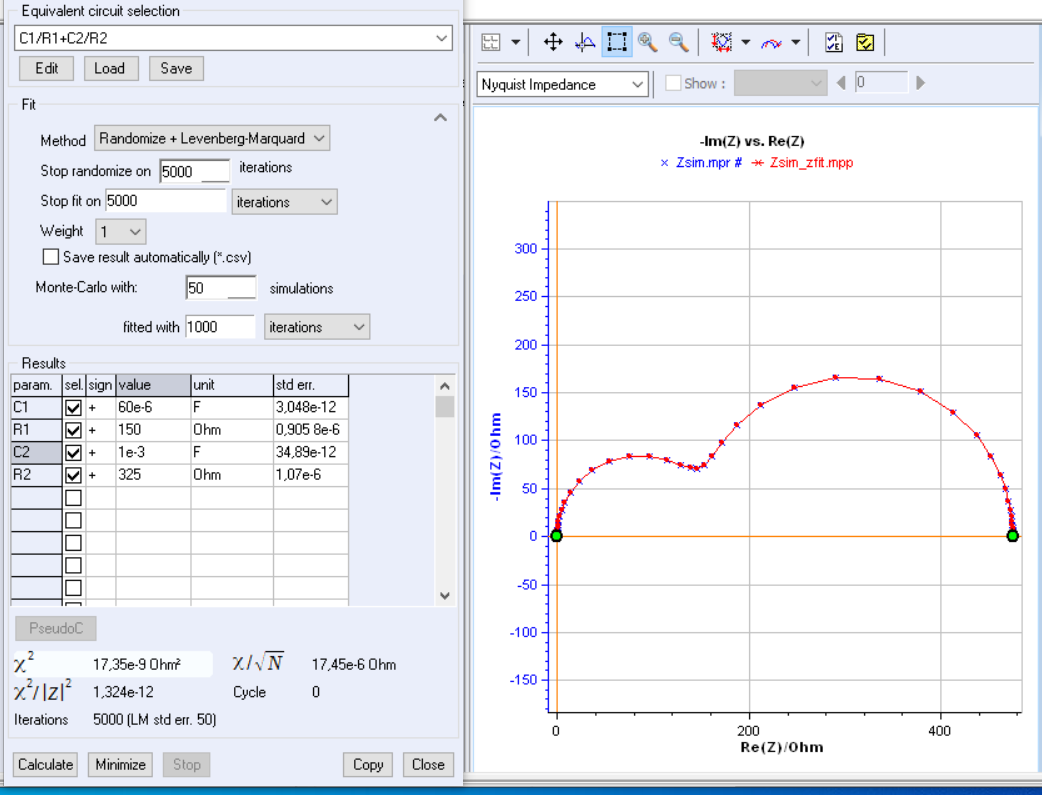
Figure 3: Fit of the impedance shown in Fig. 2 using the C1/R1+C2/R2 Voigt circuit.
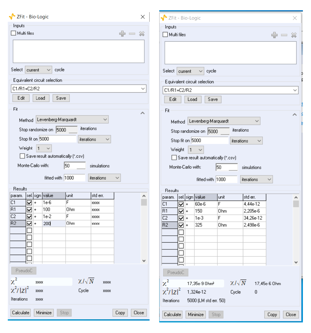
Figure 4: Initial parameters values set manually and obtained values by fitting without Randomize method.
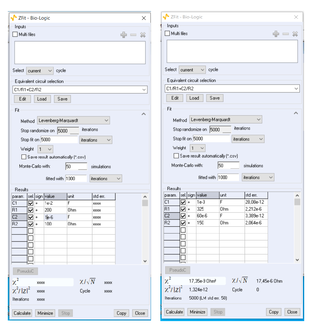
Figure 5 : Initial parameters values set manually and obtained values by fitting witout Randomize method. The obtained set of values are different from Fig. 4.
Identifiable circuit
C1/(R1+C2/R2) ladder circuit
The ZSim window for editing C1/R1+C2/R2 circuit contains links to the coding of three equivalent circuits consisting of two resistors and two capacitors (Fig. 6). The first of these circuits corresponds to the C1/(R1+C2/R2) ladder circuit shown in Fig. 7. Why is this circuit equivalent to the Voigt circuit and why can it be considered identifiable?

Figure 6 : ZSim window for editing C1/R1+C2/R2 circuit. Red rectangle: links to three equivalent circuits C1/(R1+C2/R2), C1/R1/(C2+R2) and R1/(C1+C2/R2).

Figure 7: C1/(R1+C2/R2) ladder circuit.
C1/(R1+C2/R2) circuit identifiability
The impedance of the C1/(R1+C2/R2) ladder circuit in Fig. 7 is given by:
$$Z_\text L(p)=\frac{{R1}+{R2}+{C2}\ {R1}\ {R2}\,p}{1+{C2}\ {R2}\,p+{C1}({R1}+{R2}+{C2}\ {R1}\ {R2}\, p)\, p} \tag{7} $$
and its normalized form by:
$$Z_\text L(p)=\frac{({R1}+{R2}) \left(1+\dfrac{{C2}\ {R1}\ {R2}\, p}{{R1}+{R2}}\right)}{1+({C2}\ {R2}+{C1} ({R1}+{R2}))\, p+{C1}\ {C2}\ {R1}\ {R2}\, p^2 } \tag{8}$$
Expressions (7) and (8) are no longer symmetrical with respect to the values of the components $R1$, $R2$, $C1$ and $C2$. The static gain $R1+R2$ is symmetrical, but, for example, the numerator time constant $C2(R1R2)/(R1+R2)$ of the expression (8) is not. Swapping the parameter values will lead to different impedance diagrams as shown in the diagrams of Fig. 8 calculated for the two sets (5) and (6) of parameter values.
$$Z_\text L=\frac{475. (1+ 0.102632\, p)}{1+0.3535\, p+ 0.002925\, p^2}\tag{9} $$
$$Z_\text L=\frac{475. (1+ 0.00615789\, p)}{1+0.484\, p+ 0.002925 p^2}\tag{10} $$
Impedance diagrams of the C1/(R1+C2/R2) ladder circuit will therefore be different for the two sets of parameter values as it is shown in Fig. 8. The C1/(R1+C2/R2) ladder circuit is therefore an a priori identifiable circuit, i.e. one whose parameter values can be determined by fit without ambiguity, independently from the initial values.
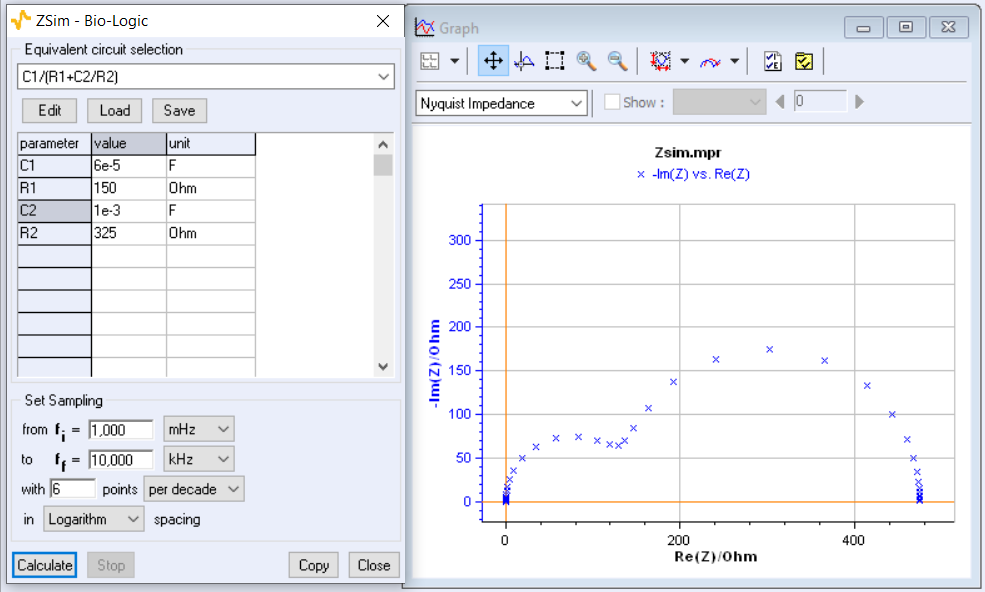
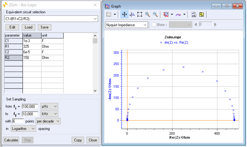
Figure 8 : Impedance diagrams of the C1/(R1+C2/R2) circuit (Fig. 7) calculated using ZSim for the set (4) and (5) of parameter values.
Conclusion
The R1/C1+R2/C2 Voigt circuit is an example of an unidentifiable circuit. Fitting an impedance diagram will result in parameter values that depend on the initial set of parameter values of the fit.
The C1/(R1+C2/R2) ladder circuit, on the other hand, is an example of an identifiable circuit and in this case, the fitting result will not depend on the initial set of parameter values. For this reason, the ladder circuit is preferred.
[1] Lai, X., Wang , S., Xie, J., Zheng, Y., Parameter sensitivity analysis and simplification of equivalent circuit model for the state of charge of lithium-ion batteries, Electrochim. Acta 330 (2020) 135239.
[2] Bruch, M., Millet, L.,Kowal, J., Vetter, M., Novel method for the parameterization of a reliable equivalent circuit model for the precise simulation of a battery cell’s electric behavior, J. Power Sources, 490 (2021) 229513.
[3] Berthier, F., Diard, J.-P., Pronzato, L., and Walter, E. Identifiability and distinguishability concepts in electrochemistry. Automatica 32 (1996), 973-984.
[4] Walter, E., and Pronzato, L. Identification of Parametric Models: From Experimental Data. Springer, New York, 1997.


