ZSim and ZFit as learning tools. Part VI – Equivalent circuits distinguishability
Latest updated: August 9, 2023This is the sixth in a series of articles about ZSim and ZFit as learning tools.
Summary:
- Part I – Acidic corrosion
- Part II – Why circle fitting is wrong?
- Part III – How to detect an inductive behaviour at low frequencies?
- Part IV – The effect of high frequency inductance
- Part V – How to choose the proper equivalent circuit?
- Part VI – Equivalent circuits distinguishability
- Part VII – Equivalent circuits identifiability
If you have ever used ZFit or ZSim in EC-Lab, you may have noticed that for some electrical equivalent circuits, another equivalent circuit is proposed (for example C1/(C2+R2) instead of C1+C2/R2). That is because these two equivalent circuits are said to be non-distinguishable from each other, but what exactly does it mean? In this article we will explain the notion of non-distinguishability, using the Voigt and the Ladder electrical circuits.
Voigt vs. ladder circuit
Voigt circuit
The impedance of the C1/R1+C2/R2 Voigt can be written:
$$ Z_\text V(p)=K\,\frac{1+a_1 p}{1+b_1 p+b_2 p^2} \tag{1}$$
with
$$ K ={R1}+{R2},\ a_1=\dfrac{({C1}+{C2}) {R1}{R2}}{{R1}+{R2}},\ b_1={C1} {R1}+{C2} {R2},\ b_2={C1} {C2} {R1} {R2} \tag{2}$$
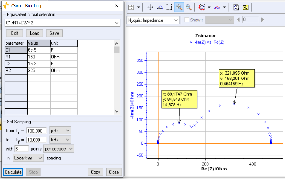
The Nyquist diagram in Fig. 1 is plotted using ZSim for the following set of component values:


Figure 1 : Impedance diagram of the C1/R1+C2/R2 Voigt circuit calculated using ZSim for the set of parameter values. Frequencies at the apex of the two arcs: $f=14.678$ Hz and $f=0.464159$ Hz.
$$C1=6 \times10^{-5}\, \text F,\ R1 =150\, \Omega,\ C2=10^{-3}\,\text F,\ R2=325\,\Omega \tag{3}$$
It has been shown [1] that the structure of the impedance of the three equivalent circuits C1/(R1+C2/R2), R1/(C1+C2/R2) and C1/R1/(R2+C2), which is composed of two resistors and two capacitors, is identical to that of the C1/R1+C2/R2 Voigt circuit. It is therefore possible to consider fitting the impedance graph of a Voigt circuit by the impedance of one of these three circuits.
Ladder circuit
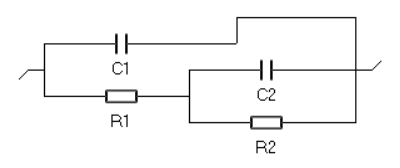
As for the Voigt circuit the impedance $ Z_\text L $ of the C1/(R1+C2/R2) ladder circuit is given by
$$ Z_\text L(p)=K\,\frac{1+a_1 p}{1+b_1 p+b_2 p^2} \tag{4}$$
With
$$K={R1}+{R2},\ a_1=\dfrac{{C2} {R1} {R2}}{{R1}+{R2}},\ b_1={C2} {R2}+{C1} ({R1}+{R2}),\ b_2={C1} {C2} {R1} {R2} \tag{5}$$


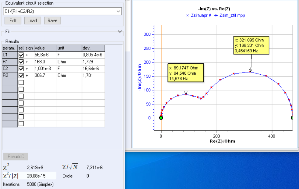
Figure 2 : Fit of the impedance shown in Fig. 1 using the C1/(R1+C2/R2) ladder circuit. Frequencies at the apex of the two arcs: $f=14.678$ Hz et $f=0.464159$ Hz.
Indistinguishability of Voigt and ladder circuits
If the structure of the impedances of the Voigt (C1/R1+C2/R2) and ladder (C1/(R1+C2/R2)) circuits are identical they are indistinguishable. By knowing the values of the parameters of one circuit, it is always possible to calculate the values of the second circuit. This leads to the same expression of the impedance and thus to the same impedance graph [1,2].
Fitting the Voigt circuit impedance by a ladder circuit
Fitting the impedance graph of the Voigt circuit (Figure 1) using the ladder circuit results in the graph shown in Figure 2. The fit leads to a value of $\chi^2$, which is identical to that of the fit with the Voigt circuit. The frequencies of the apex of the two impedance arcs are identical and the ladder circuit can therefore be used to fit the Voigt impedance graph.
Conclusion
The impedance structure of the C1/R1+C2/R2 Voigt circuit and C1/(R1+C2/R2) ladder circuits are identical and therefore they are interchangeable. However, knowing the impedance graph is not enough to know which equivalent circuit to use to fit the data. These two circuits are not distinguishable, but the article “ZSim and ZFit as learning tools. Part V How to choose the proper equivalent circuit?” will give a few guidelines on this subject.
The same conclusion is true for R1/(C1+C2/R2),the second ladder circuit, and the C1/R1/(R2+C2) Maxwell circuit. These four circuits are also not distinguishable.
[1] S. Fletcher, Tables of Degenerate Electrical Networks for Use in the Equivalent‐Circuit Analysis of Electrochemical Systems, J. Electrochem. Soc., 141 (1994) 1823.
[2] Application Note 14: ZFit and equivalent electrical circuits.