Which scanning probe electrochemistry technique?
Latest updated: June 2, 2023Understanding Scanning Probe Electrochemistry Techniques
Using the M470 it is possible to perform one of five distinct scanning probe electrochemistry techniques. With each technique offering a different insight into the sample of interest, the M470 has unmatched flexibility for measurement of the local electrochemistry of the sample. However, when faced with all this choice, at times it can be difficult for users to decide exactly which technique is best. Sometimes selecting the best technique is obvious, for example when specific data is of interest, other times users may need to consider a number of factors, like technique resolution, and sample properties. This article aims to help users determine the best technique for their experiment.
When determining the most appropriate technique there are a number of factors the user should consider. These include:
- The data of interest
- The sample properties
- The electrolyte
- The desired resolution
The data of interest
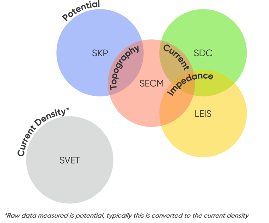
There are five distinct scanning probe electrochemistry technique types on the M470, all allowing different sample characteristics to be measured. These techniques are: Local Electrochemical Impedance Spectroscopy (LEIS), Scanning Droplet Cell (SDC), Scanning Electrochemical Microscopy (SECM), Scanning Kelvin Probe (SKP), and Scanning Vibrating Electrode Technique (SVET); for simplicity we will not include the Optical Surface Profiler (OSP) used to measure topography only. In some cases, only one technique can be used to measure the signal of interest, while in others, users may have a few options to obtain the same data. When electrochemical activity, as apparent by changes in local current, is of interest both SECM and SDC can be used to obtain this data, however unlike SDC, SECM (specifically Intermittent Contact (ic)-SECM) can also be used to measure the topography of the sample of interest. SECM and SDC also overlap in the fact that they can be used in their ac-modes to measure sample impedance. Along with LEIS, these three techniques make up the limited group of techniques to measure local impedance. Using SKP it is possible to measure the Contact Potential Difference of a sample, which is directly related to both the work function and the Corrosion Potential (Ecorr) of the sample. Finally using SVET it is possible to determine the local current density of a sample in solution, this is achieved through conversion of the raw potential data measured. The different data measured by each technique, and overlap between this data, is simplified in the Venn diagram in Fig. 1.

Figure 1: Venn diagram illustrating the overlap in the data measured by the different techniques on the M470.
The sample properties
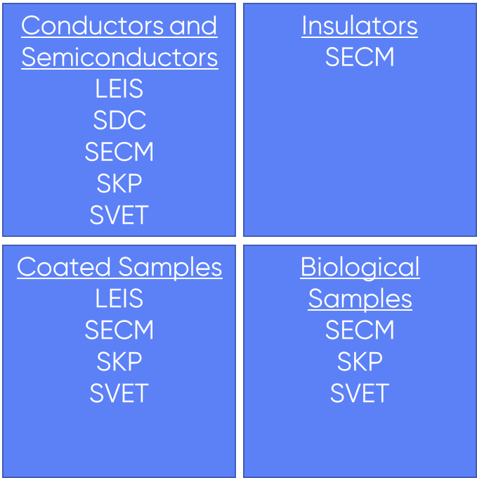
The sample can also dictate the techniques that can be used. When using LEIS and SDC the sample will always act as the working electrode of the experiment, and in SKP for the capacitor to form there must be an electrical contact between the sample and probe. In these experiments, therefore, it must be possible to make an electrical connection to the sample, e.g. through a wire. If an electrical connection to the sample cannot be made then SECM, or SVET should be considered instead. For SVET to be used without a connection to the sample, however, the sample must have a strong natural activity, if the sample is not active, or only has a weak activity, SVET should not be used. These connection requirements are reflected in the different samples which can be measured by each technique. SECM is applicable to all sample types. It can be used to measure fully conducting to fully insulating samples, and even samples in which conductive regions are embedded in an insulating array, it is even applicable to biological samples. SVET can be used with samples which are naturally active, for example corroding specimens and even biological samples. If the sample is not naturally active it can still be measured by SVET as long as it can be biased. While there is an activity requirement for SVET it can be used for coated samples to investigate coating breakdown, or scratches in the coating. LEIS is applicable to conducting and semiconducting samples, and can even be used on coated samples as long as the underlying substrate meets this requirement. When using SKP the sample is typically a conductor or semiconductor. It can also be used for coated samples, dielectric layers, and in limited cases biological samples particularly biomolecules. Finally, SDC can be used with conducting and semiconducting samples, it is not suitable for coated samples. The different sample types which can be investigated by each technique are summarized in Fig. 2.

Figure 2: The techniques which can be applied to different sample types are shown.
The electrolyte
When selecting the best technique, it’s interaction with electrolyte should be considered. For SECM, SVET, and LEIS the entire sample must be submerged in electrolyte to perform the measurement. If the sample has a poor interaction with electrolyte, for example if it corrodes rapidly, it may be better to consider a different technique. In SDC only the region of the sample exposed to the droplet is in contact with the electrolyte at a given point in time. This can be beneficial if over the period of the area scan the electrolyte could noticeably change the properties of the sample. Finally, SKP measurements are performed in air, completely free of electrolyte. This is useful if the sample will interact with electrolyte, and a snapshot of the sample characteristics at a given time are required. This is also useful if only the sample, not its interaction with an electrolyte, is of interest. When using LEIS and SVET it must also be considered that the electrolyte conductivity matters. LEIS and SVET are both dependent on Ohmic drop, and therefore electrolytes with low conductivity result in the strongest signals measured in these techniques. If a highly conductive electrolyte is required, LEIS and SVET may not be practical options.
The desired resolution
Of course, the resolution of the measurement must also be considered, as this will affect the feature sizes which can be measured. Many scanning probe microscopies have resolutions dependent on the probe size, this is no different for those techniques available on the M470. LEIS has the lowest resolution of the techniques available, this is effectively 1 mm. SECM on the other hand, has the highest resolution. The final resolution of SECM is dependent on the size of the probe used, with 1 µm probes available from BioLogic and the possibility for researchers to use their own probes. Between these extremities there is some overlap in resolution between SVET, SKP, and SDC. When using SVET the resolution is typically 100-200 µm. The resolution of SKP is dependent on the probe diameter with 150 µm and 500 µm diameters available. In SDC the size of the droplet controls the measurement resolution, with the droplet size dependent on the sample, electrolyte, and head type. It is expected that with SDC a resolution of 100 µm up to 1 mm can be achieved, depending on the setup. The resolutions of the different techniques are illustrated in Fig. 3.
When considering resolution, the required size of the scan area is also relevant. For SECM a typical measurement could be under 100 µm up to a few 1000 µm. For the other techniques a typical experiment is usually a few mm.

Figure 3: The increasing resolution of a typical measurement of each technique type is shown.
Note – there can be some overlap between the resolution of the different techniques depending on the probe used.
Summary: an overview of scanning probe electrochemistry techniques
As an overview the five distinct scanning probe electrochemistry techniques available on the M470 are summarized in Table 1.
| LOCAL ELECTROCHEMICAL IMPEDANCE SPECTROSCOPY (LEIS) | SCANNING DROPLET CELL (SDC) | SCANNING ELECTROCHEMICAL MICROSCOPY (SECM) | SCANNING KELVIN PROBE (SKP) | SCANNING VIBRATING ELECTRODE TECHNIQUE (SVET) | |
| OTHER NAMES | Local Electrochemical Impedance Mapping (LEIM); Note LEIM refers specifically to mapping experiments performed at a single frequency. | Scanning Droplet System (SDS) | Scanning Vibrating Probe (SVP); Vibrating Probe | ||
| DATA MEASURED | Local impedance | Local current, local potential, local impedance, corrosion potential | Local current, local potential, local impedance | Contact Potential Difference (CPD), which can be related to corrosion potential and work function | Local current density |
| SAMPLE TYPE | Conducting and semiconducting samples. Can be applied to coated samples | Conducting and semiconducting samples. Unsuitable for coated samples. | Fully conducting to fully insulating samples, and anything in between. | Conducting and semiconducting samples. Can be applied to coated samples, dielectrics, and biomolecules. | Samples must be naturally active, or able to be biased. Can be applied to coated samples. Can be applied to biological samples |
| ELECTRICAL CONNECTION TO SAMPLE | Required | Required | Optional | Required | Preferred |
| WORKING ELECTRODE | Sample | Sample | Probe Sample (optional) | None | Sample (optional) |
| EXPOSURE TO ELECTROLYTE | Entire sample | Sample area under droplet | Entire sample | No exposure | Entire sample |
| RESOLUTION | 1 mm (effective) | 100 µm - 1 mm | Probe size (1 µm available) | Probe size (150 µm available) | 100 - 200 µm |
| TYPICAL SCAN AREA | A few mm | A few mm | Under 100 to a few 1000 µm | Probe size (150 µm available) | 100 - 200 µm |
| ADVANTAGES | One of few techniques to measure local impedance. Direct measure of sample impedance. Quantitative analysis possible. | Only a small area of sample is exposed to electrolyte. Direct local electrochemical experiments. One of few techniques to measure local impedance. | No conductivity requirement for sample. Chemically selective. Highly flexible. One of few techniques to measure local impedance. Highest resolution. | Highly sensitive to changes in surface properties. One of few techniques to determine work function. No need for electrolyte. Non-destructive. | Can be applied to dynamic samples. Can be used for in situ studies. Non-destructive. |
| APPLICATION AREAS | Batteries, Coatings and Corrosion | Batteries, Catalysis, Corrosion and Coatings, Fuel Cells | Batteries, Biology, Catalysis, Coatings and Corrosion, Fuel Cells, Materials, Photovoltaics, Sensors | Biology, Catalysis, Coatings and Corrosion, Fuel Cells, Materials, Sensors | Batteries, Biology, Coatings and Corrosion |
When determining the best technique to measure a sample with it can help to answer the questions below:
- Is a particular signal of interest?
- Can an electrical connection be made to the sample?
- What is the sample type?
- Can the sample be exposed to electrolyte?
- What is the size of the scan area of interest?
- What sort of resolution is acceptable?
If you want discuss further which technique is best for your experiments why not contact one of our local representatives?
You may also want to read the following Learning Center articles
Related products