PEIS or GEIS or GEIS-AA? That is the question.
Latest updated: July 24, 2024There are various ways of performing Electrochemical Impedance Spectroscopy
(EIS) measurements. Which one should I choose?
Electrochemical Impedance Spectroscopy (EIS) concerns the study of a system’s response to sinusoidal electrical perturbation (for more information, please visit the BioLogic’s learning center article: “What is EIS?”). This electrical perturbation can be a perturbation of the potential (PEIS) or a perturbation of the current (GEIS), and the response is a current or a potential, respectively.
EIS measurements should be made on a system that is linear and steady-state. The linear behavior is assured by applying a signal with a small amplitude. In electrochemistry, the general notion of small amplitude is better understood with a potential input signal: without prior knowledge, a potential amplitude of 5 to 20 mV is considered small. PEIS is generally used in such experiments, however, there are times when GEIS is preferable. For example for low impedance systems such as batteries, or systems that change with time for example a corroding electrode. A third technique exists that combines the best of both worlds: GEIS-AA.
Example one: When studying low impedance systems, for example a battery
When studying a system with a low impedance, for example, a Li-ion battery with a high-frequency impedance of around a few mΩ, a small potential amplitude will generate a large current, following Ohm’s law $U/R = I$..
A potentiostat works around a regulation loop and it will be more difficult for the electrochemical instrument to carry out a measurement in a situation where small input variations cause large changes.
To illustrate this point, if you are in the shower and small turns on the shower dial create large temperature changes it can prove very difficult to find the temperature you want – and can result in much frustration!
Likewise, the potentiostat / galvanostat will be more stable with low impedance or small load systems if it controls the current, when large current amplitudes induce small potential responses following Ohm’s law: $U = RI$.
Example two: When studying a system that changes with time, for example a corroding metal or a discharging battery
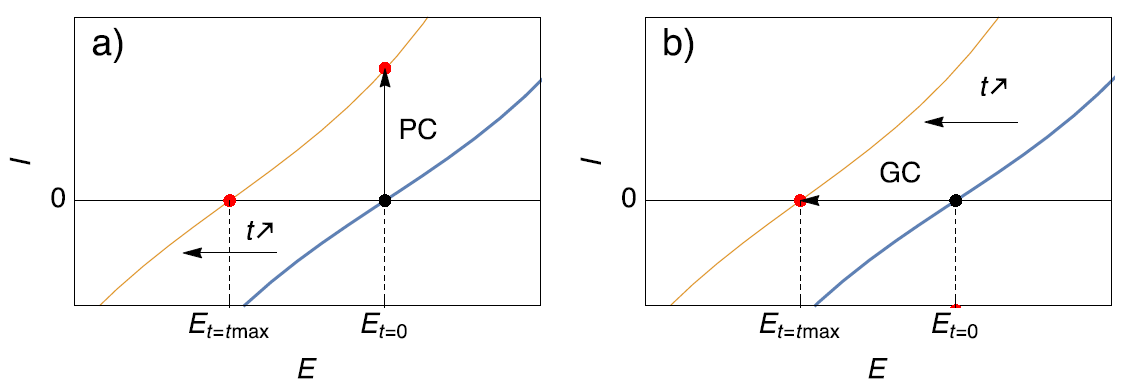
Scenario 1) A corroding electrode right after immersion can see its Open Circuit Potential (OCP) or corrosion potential change over time. When performing an EIS measurement around the corrosion potential with potential control (PC in Fig. 1a), it is possible that at the end of the experiment, the initial corrosion potential ($E_{t=0}$ in Fig. 1a) becomes anodic with respect to the actual corrosion potential of the sample ($E_{t=t_{max}}$ in Fig. 1a). In this case, the impedance measurement is performed around an anodic potential. If the impedance measurement is performed using current control (GC in Fig. 1b) and around zero current, which is equivalent to the OCP ($E_{t=0}$ in Fig. 1b), the situation is different. Even though the steady-state curve and the OCP is changing and moving towards cathodic potentials, the AC modulation is still performed around the same point on the steady-state curve ($E_{t=t_{max}}$ in Fig. 1b), that is to say around the OCP. More details are given on this subject in [1].

Figure 1. Description of the effect of (a) Potential Control (PC) and (b) Galvano control (GC) when the steady-state curve of the system is moving towards more cathodic potentials. Only galvano control at zero current allows users to follow the change of the corrosion potential.
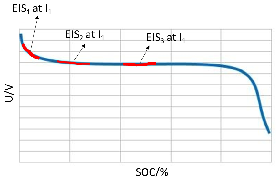
Scenario 2) Some researchers are interested in performing impedance measurements on charging or discharging batteries, sometimes named in-situ impedance measurements [2-4] as illustrated in Fig. 2.

Figure 2: Typical battery discharge curve with potential evolution during in-situ impedance measurements.
The only way to perform the type of experiment illustrated in Fig. 2 is to use galvano control EIS. First a DC current is applied to the system to partially discharge or charge the battery, then an impedance measurement is performed with current control around a non-zero DC current ($I_1$ in Fig. 2).
What is GEIS-AA and why is better than GEIS?
One could argue that even though it is preferable or even mandatory to use GEIS in the two cases mentioned above it is still difficult to know which amplitude to set to avoid a non-linear behavior of the system. This is why the technique GEIS-AA technique was developed. AA stands for Adaptive Amplitude. This is a technique that combines the best of both worlds: throughout the experiment the current is controlled, but the modulation amplitude is set in V, that is to say the input current is adapted by the potentiostat / electrochemical workstation to meet the target voltage amplitude. This way you do not have to worry about converting a potential modulation into a current modulation.
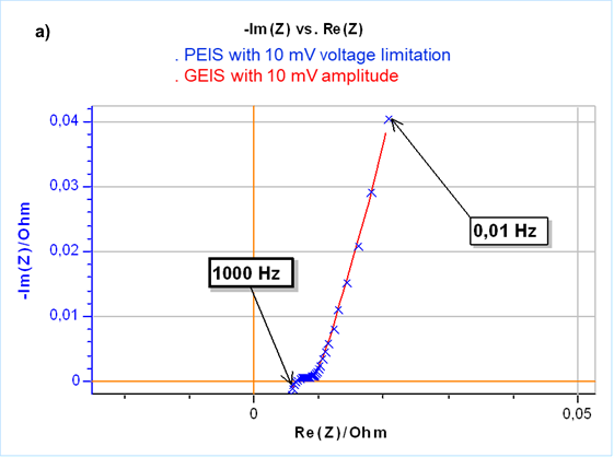
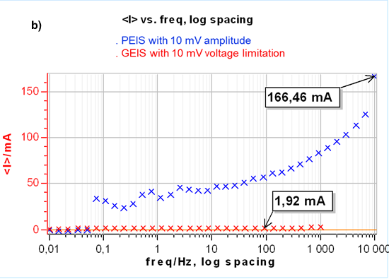
The results are the same as a potential controlled EIS measurement but use current control, which is mandatory for time-variant systems. This is illustrated in Fig. 3a. Furthermore, controlling a zero current instead of the initial OCP seems to apply a lower constraint to the cell as shown in Fig. 3b where the DC current during the impedance measurement for the PEIS is much larger than for the GEIS.


Figure 3: a) Nyquist representation of impedance measurements on a 26650 LFP battery cell using GEIS-AA (x) and PEIS (line) with 10 mV input modulation amplitude around OCP. For PEIS the OCP is measured initially at the start of the experiment and for GEIS-AA OCP is maintained by applying zero current. b) Corresponding DC current.
Further reading
Application note: Potentio or Galvano EIS – Electrochemistry & Battery – Application Note 49
References
[1] N. Murer, J.-P. Diard, B. Petrescu, Journal of Electrochemical Science and Engineering, In Press, http://dx.doi.org/10.5599/jese.725
[2] J.-P. Diard, B. Le Gorrec, C. Montella, P. Landaud, Electrochimica Acta 42 (1997) 3417-3420
[3] M. Itagaki, K. Honda, Y. Hoshi and I. Shitanda, Journal of Electroanalytical Chemistry 737 (2015) 78-84
[4] M. Itagaki, N. Kobari, S. Yotsuda, K. Watanabe, S. Kinoshita, M. Ue, Journal of Power Sources 135 (2004) 255–261