OSP101: Introduction to the Optical Surface Profiler technique
Latest updated: August 9, 2023What is the Optical Surface Profiler technique?
The Optical Surface Profiler (OSP) technique is a non-contact method to measure sample topography using a laser light. It is used on the M470 to perform standalone topography measurements, and for the input topography for height tracking measurements of other techniques.
How does the Optical Surface Profiler technique work?
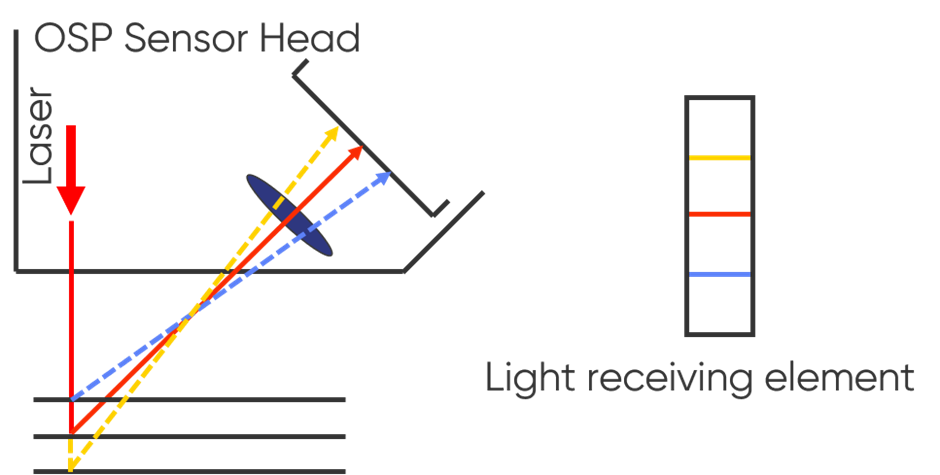
OSP uses a laser light and light receiving element to measure sample topography using 1D triangulation. In an OSP measurement the laser light is reflected off of the sample of interest onto a light receiving element within the OSP head. As the OSP head is scanned across the sample surface, the position of the reflected laser light on the light receiving element will change. When the OSP head moves from an area of higher to lower topography the reflected light moves to a higher position on the light receiving element. If the OSP head moves instead from an area of lower topography to one of higher topography the reflected light will move to a lower position on the light receiving element. This is illustrated in Fig. 1. By recording these changes in position of the reflected light on the light receiving element as the OSP head is raster scanned across the sample the final topography image is prepared.

Figure 1 : The 1D triangulation which is the basis of the OSP technique is illustrated. The red line indicates the original laser position, and its location on the light receiving element. The blue line indicates the laser position on moving to a higher topography and its new position on the light receiving element. The yellow line indicates the laser position on moving to a lower topography and its new position on the light receiving element.
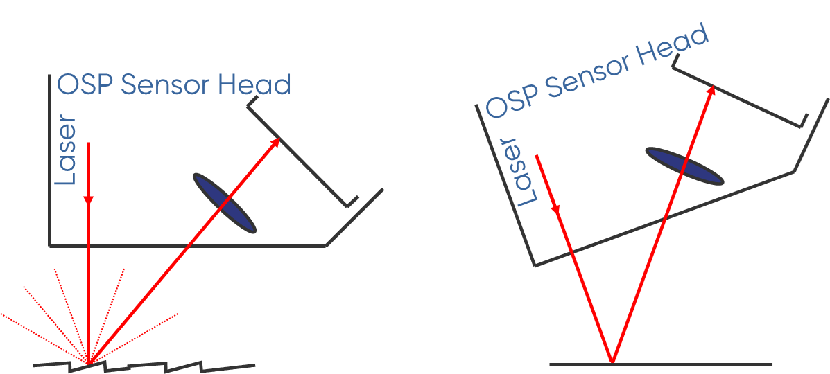
OSP can be used with either diffusely or specularly scattered light. Diffuse reflection is where the light is reflected from the surface at many angles. The diffuse reflection mode is typically used for rough samples, or samples with low reflectivity. On the other hand, specular reflection is where the light is reflected at a defined angle. The specular reflection mode is typically used for smooth, or mirror-like samples with high reflectivity. The diffuse and specular reflection modes are shown in Fig. 2.

Figure 2 : The different reflection modes of the OSP head are shown. The diffuse mode is shown on the left with an example rough surface, and the specular mode is shown on the right with an example smooth surface.
What are the components of an Optical Surface Profiler?
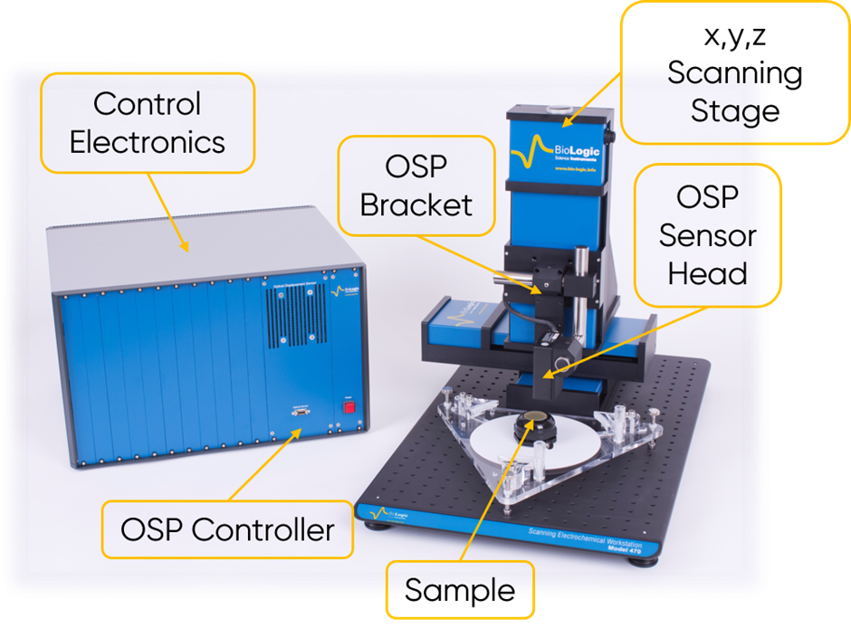
The components of an Optical Surface Profiler are shown in Fig. 3. The control electronics interface between the software and the electronic devices of the OSP instrument. The OSP head uses a small laser light which is scattered by the sample into the CCD displacement sensor. An x, y, z scanning stage is used to position the OSP head in z so it is within range of the sample, and allows for precise, automated scanning in x and y. The OSP head is mounted on the x, y, z scanning stage with a special bracket which allows the head to be co-mounted with the probe from another M470 technique. This bracket also allows the head to be better positioned for measurements if required and even angled to align it with any other probes.

Figure 3 : An Optical Surface Profiler with components annotated is shown.
Why use the Optical Surface Profiler technique?
OSP is one of a number of techniques to measure sample topography on the M470. The nature of the OSP measurement makes it the fastest of these topography options. OSP can be used to measure most samples because it is non-contact, and does not require an electrical connection to the sample. Because OSP uses a laser light, rather than a physical probe, it can be used to measure sharper changes in sample topography than can be achieved by other techniques. As with the other topography techniques on the M470, OSP is particularly useful because it can be coupled with other techniques to allow the coupled technique to be performed in height tracking mode to maintain a set probe to sample distance throughout the measurement.
- Measuring the sample topography prior to height tracking SKP measurements of a coatings system [1]
- Investigating the topography associated with biofilm formation on mild steel [2]
- Studying the swelling of dental restorative materials [3]
- Comparing the surface topography of an AZ31 magnesium alloy before and after Ultrasonic Impact Peening (UIP) [4]
Further information: Find out more
To further your understanding of BioLogic’s scanning probe techniques, visit our documents and Learning Center pages, which are regularly updated.
References:
- Borth, et al., CORROSION 75 (2019) 457-464
- S. Suma, et al., International Biodeterioration & Biodegradation 137 (2019) 59-67
- F. McCabe, S. Rusby, Biomaterials 25 (2004) 4001-4007
- D. Kajánek, et al., Mate
You may also want to read the following Learning Center articles
Related products