

Why 4-point measurements?
Latest updated: October 1, 2025The importance of 4-point connections
Whether you are a BT-Lab® Suite or EC-Lab® user, the following article may prove useful for many areas of interest, but in particular those interested in battery characterization.
Potentiostats / galvanostats and battery cyclers are instrument that can control both the current and the voltage applied to a cell. As a result, BioLogic instruments require at least 4 cables:
2 power cables (P+, P-)
2 (or 3) senses (S+, S- with or without reference)
These connections serve different purposes depending on the cycling mode:
Galvanostatic Mode (Current Control):
- Crucial for constant current charging/discharging
- Current delivered through power cables
- Sense cables measure cell voltage
- Current range selection is important
Potentiostatic Mode (Voltage Control):
- Used for constant voltage charging phases
- Voltage applied via power cables
- Sense cables provide feedback for precise voltage regulation
The 4-Point Advantage in Battery Cycling
While 2-point connections are possible, 4-point measurements are strongly recommended for high-quality battery cycling data. Here’s why:
- Eliminates cable resistance effects: Separates current-carrying leads from voltage-sensing leads
- Ensures accurate voltage readings: No current flows through voltage-sensing leads
- Compensates for connection interfaces: Accounts for extension cables, battery holders, etc.
Real-World Impact on Battery Cycling Data
Consider this example where connection cables (R1, R3) and the battery (R2) are represented as resistors:

Figure 1: Difference between 2 and 4-point measurements
In galvanostatic cycling:
- 2-point: Measured voltage includes cable resistance, skewing capacity calculations
- 4-point: Voltage measured directly at the battery terminals, ensuring accurate data
In potentiostatic cycling:
- 2-point: Applied voltage split across cables and battery, leading to inconsistent charging
- 4-point: Precise voltage control at the battery, critical for consistent CV phases
Visualizing the Difference
Electrochemical Impedance Spectroscopy (EIS) clearly shows the impact:
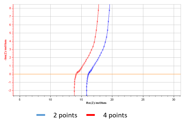
Figure 2: Nyquist diagram showing the impact of the ohmic drop induced by a 2-point measurements.
The 2-point measurement (blue curve) shows an additional ~2 mΩ resistance, which can significantly affect cycling performance analysis and battery lifetime predictions.
And Figure 3 clearly demonstrates that 2-point measurements (red curves) show less reproducibility, whereas 4-point measurements display excellent consistency with all blue curves overlapping.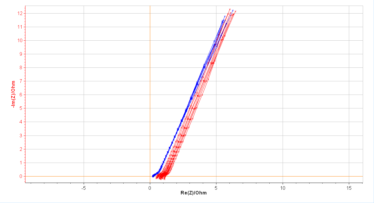
Figure 3: Nyquist diagram showing the high reproducibility of 4-point vs. 2-point measurements.
For Electrochemical Applications:
4-point connections extends far beyond battery cycling, benefiting various fields of electrochemistry. BioLogic offers a comprehensive range of equipment to support diverse applications:
Battery Research:
- Coin cell holders (CCH-1, CCH-8)
- Holders for pouch, cylindrical and prismatic, cells (PBH-125/150, BH-1i,…)
- High temperature extension cables for climate chamber
Material Characterization:
All these solutions incorporate 4-point connection designs, ensuring low connection impedance and accurate measurements across diverse applications. This approach is critical for precise data collection in AC and DC experiments, whether studying battery cycling, corrosion kinetics, electrocatalysis, or any other electrochemical phenomenon.
By offering this diverse range of 4-point enabled equipment, researchers in various fields of electrochemistry can maintain high data quality across different sample types, cell designs, and experimental conditions.


