

How to correct impedance measurements when using longer cables or a test fixture (Electrochemistry Basics Series)
Latest updated: November 15, 2024When an electrochemistry impedance spectroscopy measurement is performed, the contributions of all elements between the calibrated instrument and the device under test (DUT) are measured. So, for example, if a test is performed using a test fixture or an extension cable between the leads and the DUT, this can result in measuring additional parasitic elements (i.e. capacitance, inductance, or resistance) not directly due to the DUT.
EC-Lab® and BT-Lab® software provide a post-process analysis that compensates for the contributions of the connection interfaces (Fig. 1).

Figure 1: Compensation analysis tool in both EC-Lab® and BT-Lab® software
A 4-point connection can be used to obtain more accurate measurements than the 2-point connection, but this will not prevent the parasitic capacitance and inductance induced by the elements located between the DUT and the calibrated instrument from being measured.
When an instrument is calibrated up to the end of the standard cable, and the DUT is directly connected to the leads, a post-process compensation will serve no purpose. This post-process analysis is only useful as a means of compensating for what has not already been compensated for in calibration.
For example, VMP3, VMP-300 and BCS-800 based instruments are calibrated up to the end of the provided cables. The MTZ-35 calibration is only performed up to the front panel connectors, which means that every cable or sample holder used, for example, the Controlled Environment Sample Holder (CESH), must follow the compensation post process analysis tool.
Compensation analysis tool
The compensation analysis tool (Fig. 2) requires 1 to 3 additional data files to perform the analysis: an Open Circuit (OC) file, a Short Circuit (SC) file (optional), and a Load Circuit (LC) file (optional).
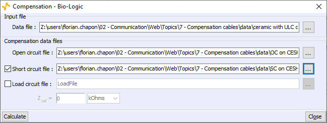
Figure 2: Interface of the compensation analysis tool.
These files will be used as blank references in the compensation process. The experiments have to be performed with exactly the same setup as the experiment of interest, meaning that only the DUT should be removed.
- For the OC experiment, the power and senses of each pole have to be shorted and the poles must be disconnected from one another (Fig. 3, left).
The PEIS technique should be used (100 mV amplitude can be used). Also, unselect the “Do not start on E overload” check box from the Safety/Adv.settings tab. - For the SC experiment, the poles must be connected together using a copper rod. The copper rod section must be thick enough to be negligible. In any case, the gap between the poles has to be the same size as the cell (Fig. 3, right).
The GEIS technique should be used (100 mA amplitude can be used).

Figure 3: Connections for the Open Circuit file (left) and for the Short Circuit file (right).
The OC experiment allows compensation for parasitic capacitance while the SC one allows compensation for parasitic inductance and resistance.
As it is a specific option, the “Load circuit file” will not be described in this article, but more information is available in the EC-Lab® and BT-Lab® Software Techniques and Applications manuals.
Material application example: EIS on a high-impedance ceramic using ULC cable and CESH
An electrochemistry impedance spectroscopy measurement is performed using the PEIS technique, an Ultra Low Current (ULC) cable on a VMP-300, and a CESH. After performing the experiment, the ceramic is removed from the CESH to perform the open circuit and the short circuit experiments for compensation. The following graph represents |Z| vs. f, for the raw uncompensated data and the compensated data (Fig. 4).

Figure 4: Comparison between raw data (blue) and data after compensation (red).
It is clearly noticeable that there is an offset between the blue and the red curves throughout the entire range of frequency, mainly due to the parasitic capacitance of the CESH, which appears in parallel, with the sample.
In this case, it is possible to determine the parasitic capacitance due to the connection interface using ZFit. To do so, “C1/R1” is used as an equivalent circuit. In the previous example, the parasitic capacitance is around 11 pF.
Long cables compensation: get rid of parasitic inductance and resistance
A measurement is carried out using GEIS on a 1.1 ohm resistor with two different setups:
- The resistor is directly connected to a VMP-300 channel booster.
- The resistor is measured using the previous setup plus a 2.5 m long, 2 wire extension cable.
The GEIS technique is preferred over the PEIS technique for low impedance cells as the 1.1 ohm resistor. The difference between PEIS and GEIS is explained in the following article: https://biologic.net/topics/peis-or-geis-that-is-the-question/
The data performed using the 2.5 m extension cable are then processed to compensate for both the parasitic resistance and inductance. The following graph represents |Z| vs. f for these three cases (Fig. 5).
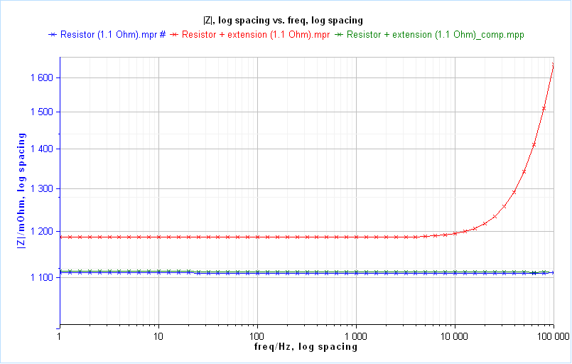
Figure 5: |Z| vs. f plot on a 1.1 Ohm resistor using a standard cable (blue),
2.5 m extension cable (red) and 2.5 m extension cable after compensation (green)
It is worth noting that the cell is only resistive at low frequencies and this is so noticeable that the resistance is entirely compensated by the process. At high frequencies, on the right, the difference of parasitic inductance can be observed. As the blue and green curves are overlapped, the parasitic contributions due to the extension cable are well compensated.
The data are fitted using ZFit. The extension cable adds an additional resistance of 88 mOhm and a parasitic inductance of 1.31 µH.


