

QCM: History and principles
Latest updated: November 15, 2024Check out our partners to perform coupled measurements: https://biologic.net/partners
The Quartz Crystal Microbalance (QCM) is a technique based on the piezoelectric properties of quartz and allows the measurement of extremely small mass changes down to a monolayer fraction. Used as an EQCM (Electrochemical QCM), it is possible to control the electrochemical potential of the studied surface and hence change and/or characterize the surface charge and/or the surface concentrations of the electroactive species.
Piezoelectricity is the property of a crystal which turns a mechanical pressure into an electrical field, which is proportional to the applied pressure. This was discovered by René Just Haüy (1743-1822), but studied more seriously by Pierre and Jacques Curie in 1880. The indirect piezo-electric effect, where a crystal submitted to an electrical field is mechanically deformed was discovered a few years after that.
There are many other piezoelectric materials, but quartz has several advantages:
- It has a low resistance to the propagation of acoustic waves
- It has a high shear modulus
- It is chemically quite stable
When an AC electrical field at an appropriate frequency is applied between the two sides of a quartz plate, the quartz starts to vibrate. The vibrational mode mostly used in a QCM is the thickness-shear mode: on each side of the nodal plan represented by a dot, the crystal plans move with the same amplitude but in the opposite direction as represented by the animated image below.

Figure 1: Shear vibration of a quartz plate submitted to an electrical AC modulation between the two Au electrodes.
At the resonance frequency, the amplitude of the displacement is maximal and is obtained when:
$$\frac{n\lambda_0}{2}=d \tag{1}\label{eq1}$$
With $n$ the harmonic mode or overtone order, $\lambda_0$ the wavelength of the acoustic wave in $\mathrm{m^{-1}}$, $d$ the thickness of the crystal plate in $\mathrm{m}$.
The wavelength $\lambda_0$ is related to the resonant frequency $f_0$ by
$$\lambda_0 = \frac{f_0}{v_\mathrm{c}}\tag{2}\label{eq2}$$
With $ v_\mathrm{c}$ the shear or tangential velocity of the crystal in $\mathrm{m\,s^{-1}}$.
Using Eqs. $\eqref{eq1}$ and $\eqref{eq2}$ give the following equation:
$$f_0=\frac{v_\mathrm{c}}{2d} \tag{3}\label{eq3}$$
Equation $\eqref{eq3}$ is referred as Equation 1 in the application note 68 [1].
A resonator or sensor is composed of a quartz plate, whose sides are coated with an electronic conductor, generally Au. Sometimes an adhesion layer between the quartz and the electrodes is added, mostly Cr or Ti. Ti is generally preferred because of its electrochemical stability and also because its contamination of the Au electrode is twice less than Cr [2]. An AC voltage is applied between the two parallel electrodes and the quartz vibrates. It is assumed that the Au electrodes are moving at the same speed as the quartz and the acoustic wave propagates in the metallic electrodes as the same speed as in the quartz.
In 1959, Sauerbrey [3] was the first one to establish a relationship between the mass change and the resonant frequency change based on Eq. $\eqref{eq3}$.
$$\Delta f_n=-n\frac{2f_{0,n}^2}{\sqrt{\mu_\mathrm{q} \rho_\mathrm{q}}}\Delta m_\mathrm{a} \tag{4}\label{eq4}$$
With $\Delta f_n$, the change of resonant frequency at the $n^{\mathrm{th}}$ harmonic in $\mathrm{Hz}$, $n$ the harmonic order, $f_{0,n}$ the resonant frequency at the $n^{\mathrm{th}}$ harmonic in $\mathrm{Hz}$, $\mu_\mathrm{q}$ the shear elastic modulus of the quartz in $\mathrm{kg\,m^{-1}\,s^{-1}}$ or $\mathrm{Pa\,s}$, $\rho_\mathrm{q}$ the quartz density in $\mathrm{kg\,m^{-3}}$, and $\Delta m _\mathrm{a}$ the areal mass of the film in $\mathrm{kg\,m^{-2}}$.
This relationship was used primarily to monitor mass or thickness change of films deposited in vacuum. In these conditions, it is considered that the film is a rigid layer and that the wave propagates in the film as the same speed as in the quartz and electrodes (Fig. 1). According to Eq. $\eqref{eq3}$, the increase of the thickness induces a change of the resonant frequency $f_0$.
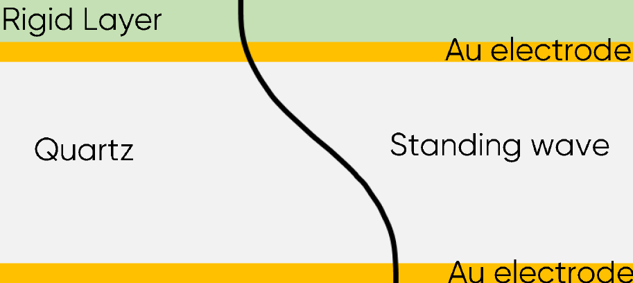
Figure 2: Acoustic standing wave across the sensor with a rigid layer.
Until the 1980s, it was believed that such a mass uptake could not be measured in solution because of the decay of the standing wave in a viscous medium. It was found that in solution, the addition of a rigid layer to the resonator has the same effect as in air or vacuum and that frequency shifts could also be successfully measured and related to thickness and mass changes [4]. The first application in electrochemistry was the electrodeposition of Ag and Cu [5].
One can see that the frequency shift $\Delta f_n$ is proportional to the areal mass $\Delta m_\mathrm{a}$ of the deposited material, which means it does not depend on the surface of the electrode.
More details on the how the frequency shift is measured and how it can be ensured that the film is rigid and that the Sauerbrey equation can be used are given in the related topics [6,7,8].
[2] J.C. Hoogvliet, W.P. van Bennekom, Electrochim. Acta 47 (2001) 599
[3] G. Sauerbrey Z. Phys. 155 (1959) 206
[4] T. Nomura, M. Okuhara Anal. Chem. Acta 142, (1982) 281
[5] S. Bruckensteinn M. Shay Electrochim. Acta 30 (1985) 1295
[6] Quartz Crystal Microbalance: Measurement principles
[7] Quartz Crystal Microbalance: When is the Sauerbrey equation valid ?
[8] Quartz Crystal Microbalance: Why measure at overtones?


