

QCM: Measurement principles
Latest updated: July 31, 2025Check out our partners to perform coupled measurements: https://biologic.net/partners
As previously described [1], the Quartz Crystal Microbalance is based on the fact that the resonant frequency of a quartz resonator changes when its thickness changes. Using the Sauerbey equation we can calculate a mass change from this frequency change. The conditions under which the Sauerbrey equation is applicable are described in a different topic [2].
There are several methods used to measure the resonant and monitor resonant frequency changes. The standard historical method using oscillator circuits is limited to resonant frequency measurements at the fundamental frequency whereas advanced systems using impedance analysis or ring-down provide dissipation and overtone measurements. A good overview of these methods is given at p. 23 in the book by D. Johannsmann [3].
In this article, we will only describe the impedance analysis method. Knowing the nominal resonant frequency of a given resonator, an impedance or rather an admittance measurement is performed by the QCM at frequencies around the nominal resonant frequency. Plotting the real part of the admittance also known as the conductance as a function of the frequency, we obtain the curve shown in Fig. 1 on the right.
At the resonant frequency, the admittance is maximal, which means the amplitude of the quartz vibration is also maximal. It can also be seen that the peak has a certain width, showing the dispersion of the resonant frequency of the quartz. The factor $\Gamma$ is the half-width at half maximum also named half bandwidth.
The bandwidth is related to the elastic properties of the resonator as well as the medium in which the crystal is vibrating.
In Fig. 1, the effect of increasing a resonator thickness is illustrated: when the thickness increases the resonant frequency shifts to lower values, as is predicted by Eq. 3 in Quartz Crystal Microbalance: principles and history [1].

Figure 1: Typical resonance curves of two crystals of different thicknesses. $f_01$ and $f_02$
correspond to a sensor of thickness $d_1$ and $d_2$, respectively, with $d_1 \lt d_2$.
Adding a rigid layer, which is assumed to be elastic, to move as fast as the quartz i.e. to have the same mechanical properties as the quartz (same shear modulus and density), has the same effect as increasing the thickness of the crystal: the resonant frequency is shifted and the bandwidth, although not constant changes only slightly as it is shown in Fig. 2.
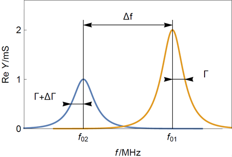
Figure 2: Typical resonance curves of (yellow) a clean sensor and (blue) a sensor with a thin rigid layer.
Note that the frequency shift $\Delta f$ is much larger than the dispersion shift $\Delta \Gamma$
As previously stated, the QCM measurement is an impedance or rather admittance measurement performed between the two electrodes of the resonator. The resonator being a piezoelectric material, the response of the system to an electrical modulation is not only electrical but also vibrational or acoustic. However, the system can be modeled by a simple equivalent circuit that is called the Butterworth-van Dyke (BvD) equivalent circuit [4, 5] (Fig. 3):
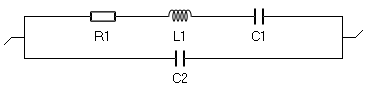
Figure 3: The Butterworth-van Dyke (BvD) equivalent circuit used to model a
quartz crystal resonator submitted to a sinusoidal electrical modulation.
The electrical components in the top branch that is called the motional branch have equivalents as motional components. The bottom branch is called the electrical branch. The Nyquist diagram of the admittance of such a circuit for typical parameters is given in Fig. 4a. The resonant frequency is the frequency for which $\mathrm{Im}(Y)=0$
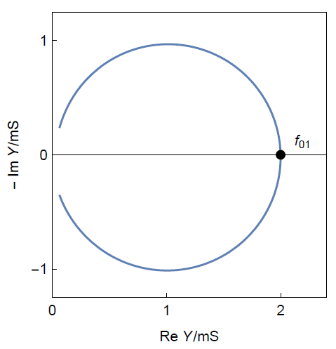
Figure 4a: Nyquist diagram of the admittance of a BvD circuit[/caption]
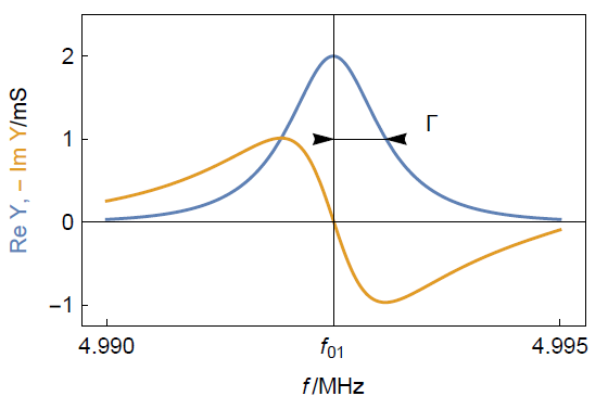
Figure. 4b. Representation of the same impedance as $\mathrm{Re}(Y),\,\mathrm{-Im}(Y)\,vs.\,f$ for
typical parameters. One can see how to determine the resonant frequency and the half bandwidth.
The relationship between the resonant frequency and the half-bandwidth with the components of the BvD circuit are the following [6]:
$$f_{01}=\frac{1}{2 \pi \sqrt {L_1 C_1}}\tag{1}\label{eq1}$$
$$\Gamma = \frac{R_1}{4 \pi L_1}\tag{2}\label{eq2}$$
$\Gamma$ is a direct measurement of the resonant frequency dispersion in $\mathrm{Hz}$ and is directly related to the acoustic properties of the film. This parameter must be measured to be able to make sure that the Sauerbrey equation can be applied to determine mass change from frequency change. We will see these aspects in more detail [3].
Standard instruments usually only give the resonant frequency changes and the resistance R1, from which it is not easy to deduce the bandwidth or the dissipation $D$ without unit:
$$D = \frac{2\Gamma}{f_{01}}\tag{3}\label{eq3}$$
These measurements are performed at the fundamental resonant frequency and can be performed at harmonic frequencies or overtones. Performing measurements at overtones lets users check the validity of the Sauerbrey equation [2]. Resonant frequencies and dissipation measurements at overtones allow also to characterize viscoelastic thin films, particles, molecules or even conformation. More details are given in [7].
- Quartz Crystal Microbalance: principles and history
- Quartz Crystal Microbalance: When is the Sauerbrey equation valid ?
- Johannsmann, in “The quartz crystal microbalance in soft matter research”, Springer, 2015
- Butterworth, Proc. Phys. Soc. London 27, (1914) 410
- K. Van Dyke, Proc. Inst. Radio Engin. 16 (1928) 742
- T. Pauporté, D. Lincot, in : Microbalance à cristal de quartz, Techniques de l’Ingénieur, (2006) P 2 220.
- Quartz Crystal Microbalance: Why measure at overtones ?


