How to avoid side reactions during battery charging/discharging?
Latest updated: October 16, 2026Introduction
Side (parasitic) reactions compete with the main charge and discharge reaction. They consume active lithium and electrolyte, build resistive layers, generate gas and, in the worst cases, create safety risks. [1,2] Aging of the electrode materials lowers the capacity and/or raises the resistance of the whole cell. The causes are coupled and act synergistically, so no single factor explains it. [1,6]
Which side reactions matter most depends on the chemistry. This article covers layered-oxide (NMC/NCA) and spinel (LMO) cathodes, and lithium iron phosphate (LFP), all paired with graphite anodes.
Side reactions are controlled mainly through electrode potentials. The standard protocol for this is CC-CV (Constant Current – Constant Voltage) [5,9], and a potentiostat/galvanostat is well suited to it because it controls and measures current and voltage precisely and switches modes without interrupting the experiment. A battery cycler can also perform these measurements and is specially designed to for battery research.
Why side reactions occur
Consider the negative electrode during charge, where two faradaic reactions can occur at the same time:
$$\mathrm{O}_1 + \mathrm{n}_1\mathrm{e}\leftrightarrow \mathrm{R}_1 \tag{1} \label{1}$$
$$\mathrm{O}_2 + \mathrm{n}_2\mathrm{e}\leftrightarrow \mathrm{R}_2 \tag{2} \label{2}$$
with two different standard potentials $E_\mathrm{th1}^- \gt E_\mathrm{th2}^-$ (Fig. 1).
Reaction $1$ is the desired one (e.g. Li insertion) and reaction $2$ the side reaction (e.g. Li plating).

Figure 1: Steady-state current vs. potential curves for simultaneous reduction reactions occurring on a negative electrode during charging.
- At charge current $I_1$, the potential settles at $E_1^-$, between $E_\mathrm{th2}^-$ and $E_\mathrm{th1}^-$. Only reaction $1$ proceeds in reduction. Reaction $2$ occurs in the oxidation reaction.
- At a higher current $I_2$, both reactions $1$ and $2$ occur in the reduction direction, as the potential $E_2^-$ is lower than both $E_\mathrm{th1}^-$ and $E_\mathrm{th2}^-$. The side reaction $2$ in the reduction direction may be unwanted, for example Li plating. [3,4]
The positive electrode behaves similarly but in reverse (Fig. 2).
An equivalent behavior can be encountered: a second, possibly unwanted, oxidation reaction may occur when the electrode potential becomes higher than $E_\mathrm{th2}^+$ (Fig.2) for a current $I_2$.
At $I_1$ the potential $E_1^+$ lies between $E_\mathrm{th1}^+$ and $E_\mathrm{th2}^+$, so only reaction $1$ occurs in oxidation. At $I_2$ the potential exceeds $E_\mathrm{th2}^+$ and the side reaction starts (e.g. electrolyte oxidation or oxygen evolution). [1,2]
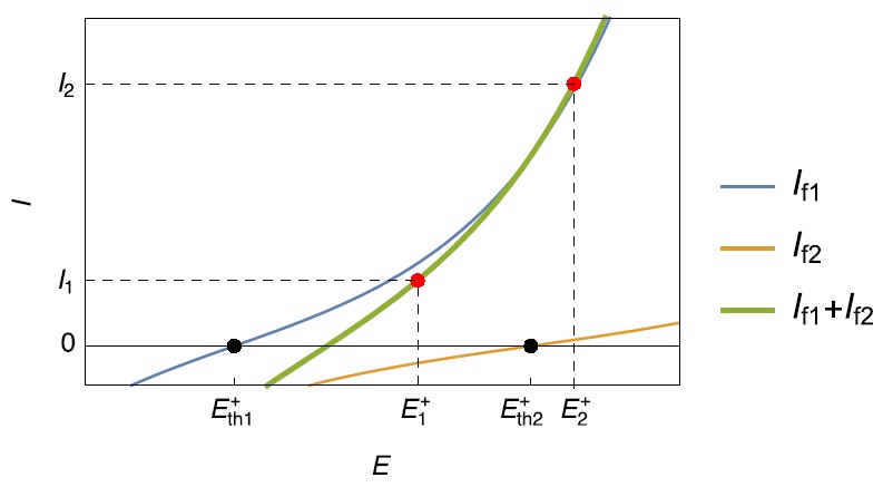
Figure 2: Steady-state current vs. potential curves for simultaneous oxidation reactions, occurring on a positive electrode during charging.
Note: The gap between electrode potential and standard potential is the overpotential. It grows with current and is amplified by ohmic drop, slow diffusion and low temperature. Fast charging is, in these terms, a push toward $I_2$. Figs. 1 and 2 are idealized steady-state curves. [5,6]
Detecting side reactions
Once the side reactions are known, strategies for detection can be implemented. They include:
- Coulombic efficiency and capacity tracking: techniques like High Precision Coulometry can quickly track capacity fade, capacity and efficiency trends and help predict aging [6].
- Voltage relaxation after charge: a plateau can indicate stripping of plated lithium. [3,4]
- dQ/dV analysis: shifts across cycles help separate lithium loss from active-material loss. In LFP/graphite cells, the flat cathode plateau means the features are typically dominated by graphite. [6]
- EIS: growth of cathode surface films and anode SEI shows up as rising interfacial resistance. In LFP/graphite cells, impedance may change little even as capacity fades, so EIS alone can miss aging. [7]
- Post-mortem or elemental analysis: iron on the anode is a sign of Fe dissolution. [8]
- Gas analysis: direct detection using multi-modal techniques such as EC-MS detect the presence of gas-forming reactions. See our partnership with Spectro Inlets for more information. [13]
- Mechanical signals during charging: measuring the change of cell pressure per unit charge (dP/dQ) can detect the onset of plating early. [3,14]
From side reactions to battery aging
Aging comes from the interplay of structural changes and side reactions at the electrode/electrolyte interface, and it is accelerated by elevated temperature, high state of charge and high charge/discharge rates. [1,2]
Negative electrode
Graphite
The graphite anode is common to all the chemistries presented, and its aging mechanisms carry over.
- SEI formation and growth. When the anode potential goes beyond the stability window of the electrolyte, solvents and salt decompose and form a Solid Electrolyte Interphase (SEI) during the first charge. The SEI is ionically conductive but electrically insulating, so it protects the electrode. If side reactions continue, deposits accumulate, the SEI keeps thickening and lithium and electrolyte are consumed further. At elevated temperatures the SEI becomes unstable and is repeatedly rebuilt. SEI thickening is also linked to the anode resistance rise and power fade. [1,2]
- Lithium plating. The reversible potential of graphite is very close to that of Li⁺/Li, so graphite is prone to plating and dendrite growth. This is aggravated at low temperature (below 25 °C) and/or high charge rate. Dendrites growing through the separator can cause short circuits and thermal runaway. [1,3,4]
- Mechanical fatigue. Lithium diffusion in and out of graphite creates diffusion-induced stress, leading to cracks, exfoliation and isolated active material. High C-rate and high SOC make this worse because of the steep lithium gradients. [1,2]
Positive electrode
NMC, NCA and LMO
- Structural disordering and phase transitions. Repeated insertion and extraction cause volume changes and mechanical stress. Phase transitions depend on high SOC and on the upper cut-off voltage. Doping (g. Al, Mg) improves cycling stability. [1,2]
- Surface films and electrolyte oxidation. At elevated temperatures, high-voltage storage drives electrolyte decomposition at the cathode, with CO₂ Surface films, including low-conductivity rock-salt-type layers, raise the interfacial resistance, which is visible in EIS. [1,2,7]
- Metal dissolution. Manganese dissolution from LiMn₂O₄ (LMO) is an important problem at elevated temperatures, through disproportionation at low SOC. Dissolved Mn migrates to the anode and is incorporated in the SEI. In nickel-cobalt-based oxides (NMC, NCA), dissolution is negligible, though a little cobalt appears on the anode when cells are charged beyond about 4.2 V vs. Li/Li⁺. [1,8]
LFP
- Iron dissolution. Trace HF in the electrolyte can attack the LFP surface and dissolve iron, and particle cracking and elevated temperature are also implicated. One study of the operating window of LFP/graphite cells proposed a mechanism accelerated at high SOC: [10] once the electrolyte additive is consumed, lithium alkoxide species form on the graphite, migrate to the cathode and drive iron dissolution. The iron then deposits on the graphite and catalyzes further electrolyte reduction and lithium loss. This is one hypothesis, not settled consensus. [1,2,8]
- Loss of active material. Cathode detachment or contact loss can also reduce active LFP, linked to corrosion of the aluminum current collector, particle cracking and thermal gradients. [2]
Full cells
LFP/graphite cells follow a simpler aging pattern occurring primarily at the anode.
- Lithium loss is the dominant degradation mode. In calendar aging, SEI growth on the graphite anode dominates, accelerated by temperature and high SOC. Mechanistic modeling of this system centers on three processes: SEI growth, lithium plating and gas generation. [1,5,12]
- Capacity fades more than impedance rises. Aging is one of the main causes of capacity fade, often without notable impedance increase. Depending on temperature, the capacity loss was attributed to SEI growth or lithium plating. [6,7]
- Temperature decides the mechanism. In low-temperatures, significant plating can occur at −18 °C and is considered the main cause of capacity loss, while at 0 °C only trace plating can be seen and plating plus SEI thickening seems to dominate. [3,4,11]
Summary of mechanisms, triggers and consequences
| Mechanism | Main triggers | Consequence | What helps |
| SEI growth (graphite anode, all chemistries) [1,2] | Anode potential beyond electrolyte window, elevated temperature, high SOC | Lithium loss, resistance rise | Temperature control, lower storage SOC, suitable electrolyte |
| Lithium plating [1,3,4] | Low temperature (<25 °C), high charge rate | Lithium loss, dendrites, short-circuit risk | Lower rate, warmer cell |
| Anode mechanical failure [1,2] | High C-rate, high SOC | Cracking, isolated active material | Moderate rates and SOC window |
| Cathode phase transitions (NMC/NCA/LMO)[1,2] | High SOC, high cut-off voltage, overcharge | Capacity fade | Control cut-off voltage, doping |
| Electrolyte oxidation (layered-oxide cathodes) [1,2] | Elevated temperature, high storage potential | Gas, surface film, resistance rise | Temperature and cut-off control, alternative salts, low protic impurities |
| Mn dissolution (LMO) [1,8] | Elevated temperature, HF, deep discharge | Active-material loss, SEI contamination | Avoid deep discharge, blend with NMC/NCA, alternative electrolyte |
| Fe dissolution (LFP) [2,8] | HF, particle cracking, elevated temperature, high SOC | Active-material loss, iron deposits on graphite, extra lithium loss | Temperature control, moisture/HF control, SOC window |
How CC-CV helps limit side reactions
The two examples shown in Fig. 1 and 2 show that unwanted reactions, that may deteriorate the battery, can be avoided during charge or discharge by preventing the electrodes from reaching a certain potential or the battery from reaching a certain voltage value. Using the constant current-constant voltage (CC-CV) charging technique, the presence of these side reactions can be avoided (Fig. 3).
CC-CV has two phases (Fig. 3):
- CC phase: a fixed current is applied until the voltage reaches $U_\mathrm{lim}$.
- CV phase: the instrument holds $U_\mathrm{lim}$ and the current decays toward zero. Charging ends when the current falls below a cut-off (commonly C/20 to C/50) or a time limit is reached. [5,9]
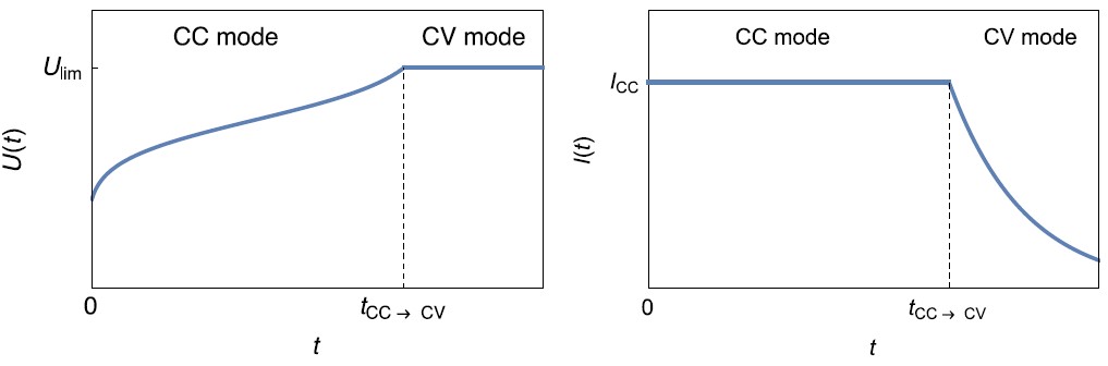
Figure 3: Left: $U(t)$ vs. $t$ curve and Right: $I(t)$ vs. $t$ during the charge of a battery using CC-CV technique.
Choosing the parameters
Ulim: this must match the cell chemistry (see table below). It is a direct lever against cathode phase transitions and electrolyte oxidation, and it must also account for the plating margin of the negative electrode. [3,4,9]
- CC current: lower currents mean smaller overpotentials and lower plating risk, at the cost of charge time. [5,9]
- Cut-off current and hold time: the CV phase keeps the cell at high potential, which favors electrolyte decomposition. Avoid unnecessarily long holds and avoid storing cells fully charged. [5,9]
Adapting the protocol to cell chemistry
| Chemistry | Typical upper limit (per cell) | Typical lower limit (per cell) |
| NMC/NCA | ~4.2 V (some high-voltage variants 4.3–4.4 V) | ~2.8–3.0 V |
| LFP | ~3.65 V | ~2.5 V |
Note: These are typical datasheet values. Always use the manufacturer’s limits for the specific cell. An NMC setting applied to an LFP cell would badly overcharge it. LFP’s flat plateau means little voltage warning precedes this.
What the LFP voltage plateau means for charging protocols
Voltage is a poor SOC indicator. Most of the capacity sits on a very flat plateau around 3.2–3.3 V, which makes SOC estimation from voltage hard but makes voltage-based charge termination simple. The current cut-off in the CV phase becomes more important than voltage for deciding when the cell is full.
- Cell voltage hides the anode. On the plateau, the cathode potential barely changes, so small changes in cell voltage are largely anode behavior. High-resolution voltage measurement and a reference electrode are especially valuable in LFP research. [3,6]
- CC-CV at fast-charging rates. At high current, larger overpotentials mean the cell reaches Ulim at a lower SOC, so more of the charge is delivered in the slower CV phase. [5,9]
Limits of CC-CV
Cell voltage is not electrode potential. Ucell = E+ – E–. A two-electrode measurement can’t show which electrode is near its limit, and the negative electrode can reach plating potentials at a cell voltage that looks safe. This matters most at high current rates and for LFP. [3,4]
- Aging shifts the margins. As resistance grows, the same current produces larger overpotentials. [6,9]
- Not all aging is potential-driven. Mechanical fatigue, dissolution and thermally accelerated chemistry are only partly addressed by a voltage limit. [1,2]
Concluding remarks
Side reactions are a result of the conditions at the electrode potentials, not only cell voltage, and their effects can be studied by varying cut-off voltage, charge rate, temperature and time spent fully charged. The graphite anode is the common weak point because LFP/graphite cells primarily age due to SEI growth and lithium plating, which limits fast charging. Whereas NMC/LMO cells add cathode-side issues (phase transitions, electrolyte oxidation, Mn dissolution), while LFP adds iron dissolution and a flat plateau that hides the anode.
References
- Vetter, J.; Novák, P.; Wagner, M. R.; Veit, C.; Möller, K.-C.; Besenhard, J. O.; Winter, M.; Wohlfahrt-Mehrens, M.; Vogler, C.; Hammouche, A. Ageing mechanisms in lithium-ion batteries. Power Sources 2005, 147 (1-2), 269-281. DOI: 10.1016/j.jpowsour.2005.01.006.
- Lin, C.; Tang, A.; Mu, H.; Wang, W.; Wang, C. Aging Mechanisms of Electrode Materials in Lithium-Ion Batteries for Electric Vehicles. Chem. 2015, 104673. DOI: 10.1155/2015/104673.
- Chen, R.; Miao, S.; Jia, Y.; Zhang, X.; Peng, J.; Zhang, K.; Wu, F.; Zhao, J.; Li, Z.; Cai, W. A review of detecting Li plating on graphite anodes based on electrochemical methods. Mater. Chem. A 2024, 12, 33427-33447. DOI: 10.1039/D4TA05871B.
- Hu, D.; Chen, L.; Tian, J.; Su, Y.; Li, N.; Chen, G.; Hu, Y.; Dou, Y.; Chen, S.; Wu, F. Research Progress of Lithium Plating on Graphite Anode in Lithium-Ion Batteries. J. Chem. 2021, 39 (1), 165-173. DOI https://doi.org/10.1002/cjoc.202000512
- Overview of multi-stage charging strategies for Li-ion batteries. Review, 2023 Journal of Energy Chemistry 2023,84,228-241. 1016/j.jechem.2023.05.023
- Birkl, C. R.; Roberts, M. R.; McTurk, E.; Bruce, P. G.; Howey, D. A. Degradation diagnostics for lithium ion cells. Power Sources 2017, 341, 373–386.
- Gaberšček, M. Understanding Li-based battery materials via electrochemical impedance spectroscopy. Commun. 2021, 12, 6513.
- Gilbert, J. A.; Shkrob, I. A.; Abraham, D. P. Transition metal dissolution, ion migration, electrocatalytic reduction and capacity loss in lithium-ion full cells. Electrochem. Soc. 2017, 164, A389–A399. DOI:10.1149/2.1111702jes
- Keil, P.; Jossen, A. Charging protocols for lithium-ion batteries and their impact on cycle life – An experimental study with different 18650 high-power cells. Energy Storage 2016, 6, 125–141. DOI:10.1016/j.est.2016.02.005
- Zsoldos, E.; et al. The Operation Window of Lithium Iron Phosphate/Graphite Cells Affects their Lifetime. Electrochem. Soc. 2024, 171, 080527. DOI: 10.1149/1945-7111/ad6cbd.
- Rauhala, T.; Jalkanen, K.; Romann, T.; Lust, E.; Omar, N.; Kallio, T. Low-temperature aging mechanisms of commercial graphite/LiFePO₄ cells cycled with a simulated electric vehicle load profile: a post-mortem study. Energy Storage 2018, 20 pp. 344-356. DOI:10.1016/J.EST.2018.10.007
- Zhe Lv , Huinan Si , Zhe Yang , Jiawen Cui , Zhichao He , Lei Wang , Zhe Li ,Jianbo Zhang Simplified Mechanistic Aging Model for Lithium Ion Batteries in Large-Scale Applications. Materials 2025, 18 (6), 1342. DOI: 10.3390/ma18061342.
- Thornton, D. B.; Davies, B. J. V.; Scott, S. B.; Aguadero, A.; Ryan, M. P.; Stephens, I. E. L. Probing Degradation in Lithium Ion Batteries with On-Chip Electrochemistry Mass Spectrometry. Chem. Int. Ed. 2024, e202315357. DOI: 10.1002/anie.202315357.
- Huang, W.; Ye, Y.; Chen, H.; Vilá, R. A.; Xiang, A.; Wang, H.; Liu, F.; Yu, Z.; Xu, J.; Zhang, Z.; Xu, R.; Wu, Y.; Chou, L.-Y.; Wang, H.; Xu, J.; Boyle, D. T.; Li, Y.; Cui, Y. Onboard early detection and mitigation of lithium plating in fast-charging batteries. Commun. 2022, 13, 7091. DOI: 10.1038/s41467-022-33486-4.