Connection to the cell – Part 2 – Multi-electrode measurement
Latest updated: June 2, 2023This article is the second in a third part series of three articles about connection modes.
BioLogic potentiostats are always connected to an electrochemical cell using the same cable leads, but these can be connected differently depending on the required application.
Summary & general information: which connection mode to use?
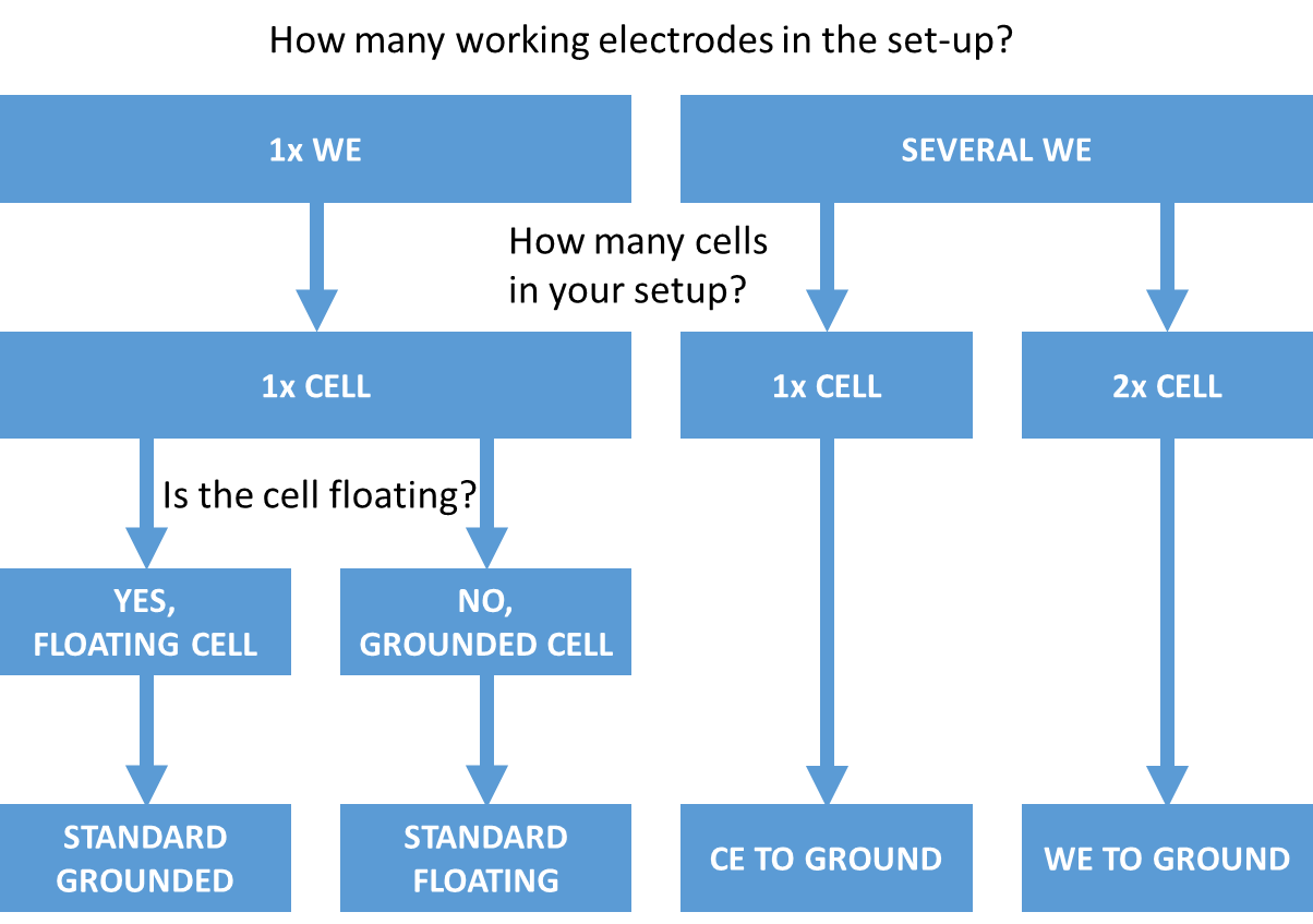
The following flow diagram indicates which connection mode you should use for your application.

Summary:
Multi-electrode application
One of the connection modes is the “CE to ground” connection mode. This connection mode has been intentionally designed to allow the user to perform multi-electrode measurements using several working electrodes (WE) in the same electrochemical cell, and one common counter electrode (CE) along with a common reference electrode. This configuration is commonly found in the sensor development field or in corrosion testing. This allows the screening of several samples simultaneously (saving you time) in the same conditions (meaning there is no variability during the measurement, same temperature, same solution, etc).
NOTE: By way of an example, a rotating ring-disk electrode (RRDE) uses a ring and a disk as working electrodes for only one reference electrode and one counter electrode. For this application, two synchronized channel boards can be used as a bi-potentiostat.
Other uses of the “CE to ground” connection mode: An alternative to the floating connection mode
Experimental electrochemistry in an autoclave or a pipeline may require the counter-electrode (CE) to be connected to the ground, because, in such scenarios, these are used as counter-electrodes. More generally, when the CE is for some reason connected to the earth ground through a weak or strong conductive path, a possible channel connection is the CE to GND.
NOTE: It is also possible to use the “floating” mode, which is available on premium range potentiostat / galvanostat for this type of application.
The Difference between “Standard” and “CE to ground” modes
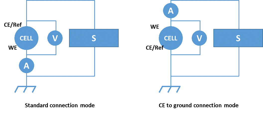
For the sake of clarity, the cell is simplified to a two-electrode cell with a common counter and reference electrode. By default, the standard connection mode is used because it provides the maximum measurement performance and is the best choice for most practical situations involving standalone cells. A potentiostat / galvanostat (S) is used for both an ammeter (A) for current measurement, and a voltmeter (V) to measure the voltage. The position of the elements and their polarity differs depending on the selected connection mode.
For both connection modes, the ammeter is placed on the WE side, and the voltmeter is connected between the WE and the Ref. The main difference is that in CE to ground mode the cell connection is reversed to link the counter electrode to the ground (Figure 1).

Fig.1: Differences between Standard and CE to ground connection
Why use the CE to Ground connection mode: RRDE example
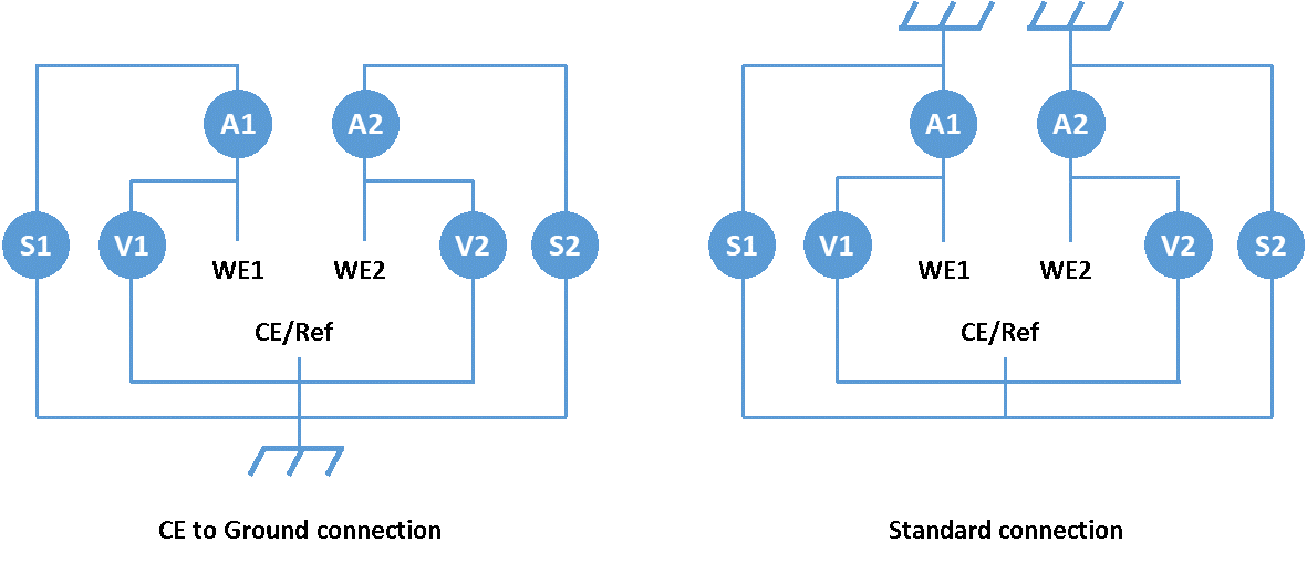
To illustrate the reason why the CE to Ground connection mode is mandatory for multi-electrode experiments, we will consider a two working electrode setup, similar to an RRDE experiment (Figure 2).

Fig.2: Bi-potentiostat used on a multi-electrode setup. Differences between CE to Ground and Standard connection
The main issue of using standard connections for this purpose is that sources S1 and S2 can be short-circuited if the channels are “grounded”(non-floating), because of the two grounds linked together through the earth (Part 1 – What is the ground? ). This will lead to an overload. This is why the CE to Ground connection mode is well suited to this application.
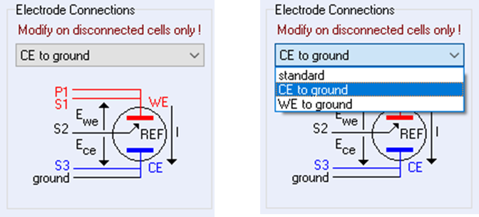
NOTE: The connection mode used can be modified in EC-Lab using the “electrode connections” menu, which is located in the “Safety/Adv. Settings” tab (Figure 3).
Fig 3. “electrode connections” menu of a VMP-300 based technology instruments.
This menu can display up to four connection modes: standard, CE to ground, WE to ground (premium range only), and when a booster is linked to the channel board, a High Voltage connection mode.
Related products
