

Get more from your potentiostat. Understanding bandwidth & its effect on measurements (Electrochemistry basics series)
Latest updated: March 6, 2025Introduction
The electronics that sit behind a potentiostat / galvanostat is often misunderstood. In this article, we will explain what bandwidth is, its effect on your measurements, and, more importantly, how to correctly set it to enhance the quality of your electrochemical measurements.
In simple terms, bandwidth can be described as the parameter that defines how fast the potentiostat or the battery cycler is able to react. This is the instrument’s regulation loop, and concerns more specifically, the regulation loop of the control amplifier (CA). The regulation loop is the process that makes sure that the instrument control correctly responds to the user’s settings.
The three main parameters that affect the regulation loop within a potentiostat are :
- The control amplifier bandwidth (represented by CA in 1)
- The cell itself (represented by WE (working electrode); CE (counter-electrode) & RE (reference electrode) in 1). Slow bandwidths are usually recommended for capacitive cells,
- The set current range (represented by Rm in 1). If the user needs a current booster, the instrument has to be slowed down, which means that the bandwidth has to be reduced.
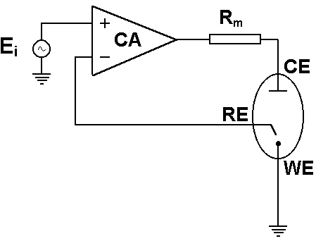
Fig. 1: Sketch of basic potentiostat design. The cell:
WE: Working Electrode
CE: Counter Electrode
RE: Reference Electrode
The instrument:
CA: Control Amplifier;
Rm: the current range shunt resistor
The experiment settings:
Ei: Setpoint voltage
NOTE: Bandwidths differ according to the control mode i.e. Potentiostatic or Galvanostatic.
Current range and settings for a given cell:
- If the bandwidth is too fast, you may get oscillation.
- If the bandwidth is too slow, you will smooth out the cell response.
NOTE: The bandwidth does NOT act as a filter. A filter affects only the measurement whereas a bandwidth affects the regulation loop of the instrument (cell control) be it a potentiostat or a battery cycler.
The context: how to carry out a test for a potentiostat or battery cycler with different bandwidths…
Figure 2 below demonstrates steps of +200 mV voltage step applied to a Li-battery with different bandwidths. This example demonstrates that bandwidth 6 leads to oscillation whereas slower bandwidths lead to good measurements.
With bandwidth 1 (the slowest), we see that the time constant is limited by the instrument and not by the cell. For bandwidth 5 (medium), the measurement is not limited by the regulation loop of the potentiostat or battery cycler, but by the cell. So, in the example shown above, the appropriate bandwidth i.e. the fastest without any oscillation is bandwidth 5.
NOTE: Depending on the sampling rate of the measurement, only the oscillation envelope may be seen.

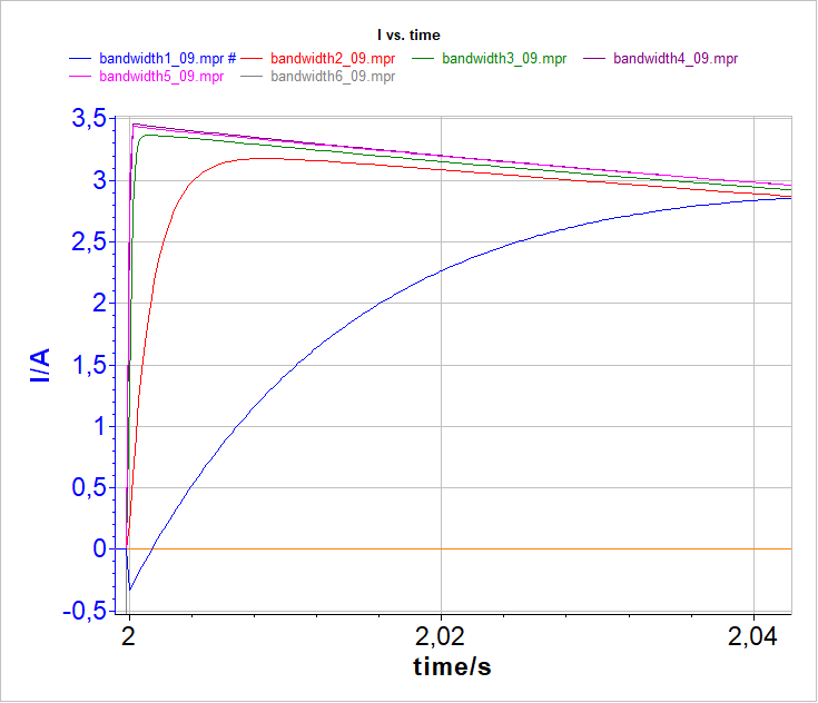
Fig. 2: Voltage pulse carried out with VMP3 potentiostat equipped with a current booster at different bandwidths (1; 2; 3; 4; 5; 6). Bottom: zoom on the slowest bandwidths.
For Electrochemical Impedance Spectroscopy (EIS) measurements, the bandwidth should be set in relation to the maximum frequency. In the MHz range, the user has to set a fast bandwidth.
Tips to optimize your setup
The first thing to do when your potentiostat starts oscillating is to admit that the electrochemical cell may be responsible for this behavior. For more information, please read app note 4.
If you want a quick solution to your problem without going into detailed stability analysis, you can follow these steps:
- Change the Bandwidth factor. Start with a lower value. If decreasing the bandwidth factor does not work, try to increase it. The faster, the better.
- For EIS measurements at high frequencies, the regulation loop has to be fast, so a fast bandwidth is required.
- It is the same for potentio/galvano-dynamic measurements carried out at high scan rates – fast bandwidths must be set.
- The hardware ohmic drop compensation slows down the regulation loop, so in some cases, you may need to decrease the bandwidth.
- For Premium range potentiostats, adjust bandwidths 7, 8, 9 first . Then, if the measurement still shows signs of oscillation try the advanced bandwidths 1 to 6.
If the bandwidth modification does not solve your issue, follow these recommendations:
- Check your reference electrode. Make sure that the inside solution of the reference electrode has good contact with the bulk electrolyte of the cell. If the porous junction is not wet, then the electrode may have enormous impedance and together with the electrometer input capacitance, may introduce a supplementary phase shift on the feedback.
- Choose a higher current range. Since the current measuring resistor is part of the feedback, the lower it is, the more stable the system. But there is a limit on how small a measuring resistor can be. If it is too small, you will not be able to detect the low currents.
- If, after the previous steps, the system is still unstable, then you have to think about adding a resistor in series with the working electrode. When the cell is highly capacitive and you have an idea about the double layer capacitance, then use Equation 22 of app note 4 to determine the resistor value.
- Reduce, if possible, the surface of the working electrode. Since the double layer capacitance is proportional to the electrode area lowering the surface will reduce the capacitance, which is generally responsible for the instabilities.
- Reduce also, if possible, the impedance between the counter and the reference electrode. This includes the interfacial impedance of the counter electrode and the solution resistance between the two electrodes.


