

Connection to the cell – Part 3 – Permeation cell measurements (Working Electrode to Ground)
Latest updated: August 6, 2025This article is the third in a three-part series about connection modes.
To address the permeation application (one working electrode shared by two different cells), a specific control mode must be set.
Summary & general information: which connection mode use?
The flow diagram below indicates the most suitable connection mode for your application.

Summary:
Permeation cell application
A permeation cell enables the study of the diffusion of a species through a solid. To do so, the studied material is used as a membrane separator and the species concentration evolution is studied on both sides of the membrane. On one side, named the “entry side”(the first cell), a concentration of species is generated while, due to the diffusion of the species inside the material, a concentration change is observed on the other side, named the “detection side” (the second cell – Figure 1).
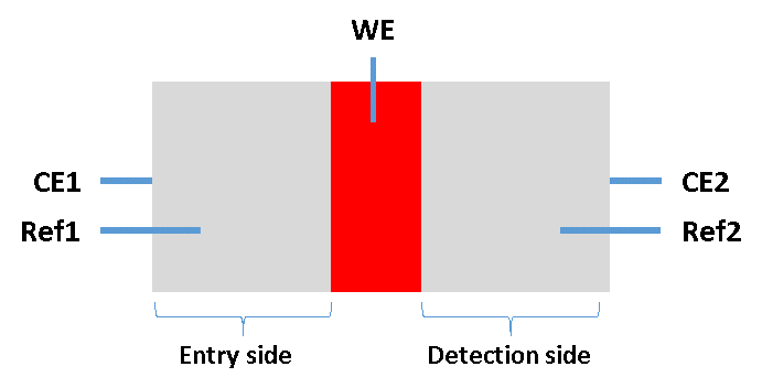
Fig 1. Schematic of a permeation cell. In red, the studied material is used as a working electrode. In grey, the entry and detection sides are visible.
The time lag after which the concentration change appears at the detection side is a measure of the diffusion coefficient. For this purpose, two potentiostat / galvanostat channel boards are required, one for each cell. Each cell includes one reference (Ref) and one counter electrode (CE). A common working electrode (WE) is shared by the two cells.
Other uses of “WE to ground” connection mode: QCM application
The “WE to Ground” connection mode is also highly recommended when the working electrode (WE) is for some reason connected to the earth ground through a weak or strong conductive path. This is especially true for certain electrochemical quartz crystal microbalance (EQCM) instruments. Even if both the potentiostat and the EQCM are using a “floating” type connection, the isolation resistance between the ground and the earth ground is not infinite (see Part 1: What is the ground?).
Differences between “WE to ground” and “CE to ground”
As seen in Part 2 of this series of articles, we have seen the reasons why it is necessary to use a common ground to avoid ground loops. The “CE to ground” connection mode is well designed for applications requiring only one reference electrode because of a common counter electrode. In the case of permeation applications, it is mandatory to have two separate reference electrodes to be able to study two different electrochemical interfaces at the same time: this is the reason why we use a common working electrode (Figure 2).
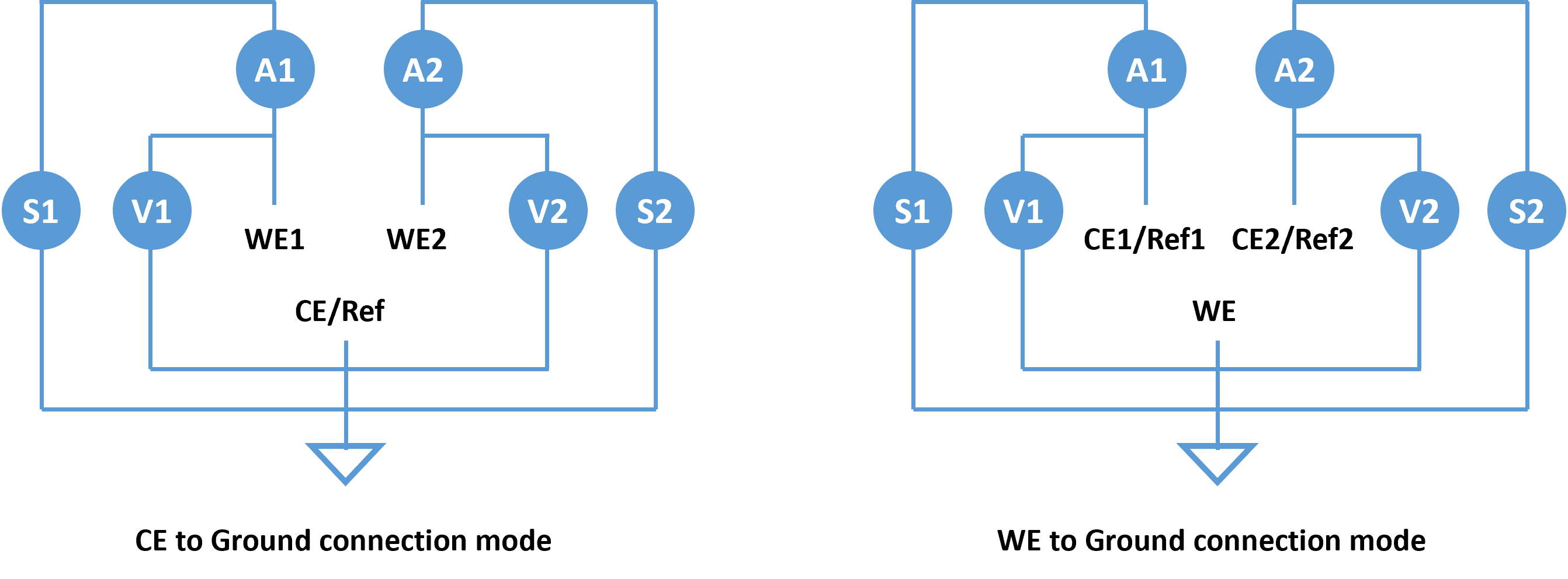
If the ammeter is placed on the WE side, the error occurring on the current measurement can be significant at low currents, even when the channel board uses a “floating” connection type. This is because there is always a voltage drop over a real ammeter, a fraction of the WE current will pass through the isolation impedance and not through the ammeter inducing measurement errors. This is the reason why the ammeter is placed on the CE side (Figure 3).
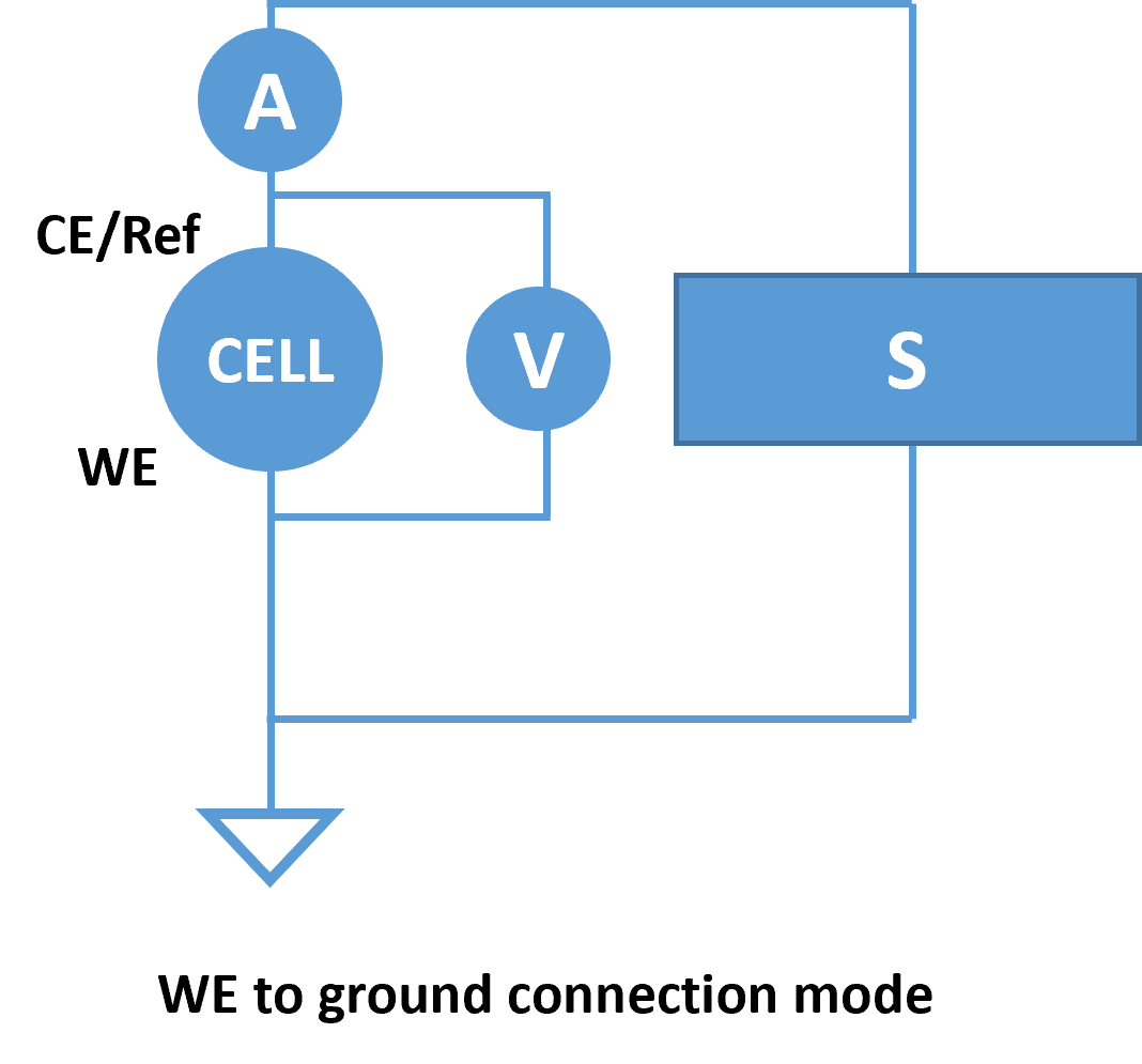
NOTE: In theory, it is possible to have the WE connected to the ground with the ammeter placed on the same side. This will only work for high currents as the internal resistance of the ammeter is much lower than the module of the isolation impedance: most of the current will pass through the ammeter.


