

Potentiostats: Obtaining high quality measurements (Electrochemistry Basics Series)
Latest updated: October 6, 2025As electrochemical techniques are highly sensitive, precautions must be taken to prevent the collection of false or erroneous data resulting from experimental errors. This article gives tips on how to improve the quality of electrochemical measurements when using your potentiostat, from optimizing the setup of your electrochemical workstation, or the connection interfaces, to the geometry of the cell itself.
Optimizing the setup
Protect the electrochemical cell
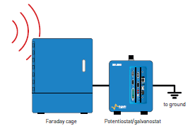
Measurement quality can be affected by electromagnetic perturbations due to electrical networks, or to the presence of other instruments nearby. To avoid this issue, a Faraday cage is highly recommended, especially for low current measurements below 10 µA. The Faraday cage (such as the BioLogic FC-45 pictured below) must be connected to the ground to create an equipotential shielding.
Note: it is possible to verify the presence of electromagnetic perturbations by carrying out an Open Circuit Voltage measurement using a high sampling rate (200µs), and performing a Fourier transform to characterize the frequency of the noise.
Get rid of noise
If the Faraday cage cannot be used, there are two other ways to get rid of noisy results:
Averaging
Using averaging can significantly reduce your data noise. The standard deviation of the signal, using averaging, is equivalent to the standard deviation of the original signal divided by the square root of the number of average used.
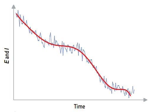
Example: If noisy measurements are obtained with your potentiostat, to decrease the noise by a factor of two, four times more data points must be averaged.
Filtering
If averaging cannot be used, low-pass analog filtering can be used inside the safety/advanced settings tab of your potentiostat software such as EC-Lab.
It is also possible to reproduce the effect of this filter post-process thanks to the software’s analysis package.
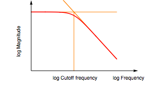
Note: a low-pass filter removes all frequencies above the one selected. Only VMP-300 based technology potentiostats provide analog filtering (hardware).
The quality of the reference electrode (RE)
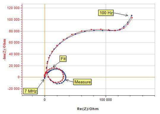
The effect of reference electrode quality is often underestimated. A damaged or worn reference electrode, with an impedance higher than 1 kOhm, may induce strange behaviors while performing EIS measurements at high frequencies (MHz frequencies).
Pay attention to connection interfaces
2 vs 4-point measurements
A 4-point connection to an electrochemical workstation separates the current-carrying leads from the voltage-sensing leads. This ensures that there is no current passing through the voltage-sensing leads, or through connectors, cables, or connection interfaces (extension cables, battery holders etc.) and helps avoid voltage drops. By using this type of connection, only the cell potential will be measured.
For more details on this subject, please see the 4 point article in our Learning Center.
Inductive effect
For high current experiments using more than 10 A, the electromagnetic field around the wire may induce an inductive effect. Because of this inductive effect, the contact resistance or internal resistance of the electrochemical cell will be overestimated. To solve this problem, we recommend you twist the current-carrying leads together to compensate for the electromagnetic field.

Note: by adding wiring between the cell cables and the cell, you will encounter the inductive effect and also add contact resistance. Because of both combined phenomena, the contact resistance or internal resistance will be overestimated.
Beware of the cell’s geometry
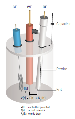
The ohmic drop, also called IR drop, describes the exceeding potential due to the electron flow through a material. In electrochemistry, it often refers to the potential induced by the resistance of the electrolyte, or any other interface such as surface films or connectors.
For a voltammetry experiment on a given system, the applied potential, in the presence of an ohmic drop, should abide by the following equation:
$E(t)=E_i+v_b t-R_ΩI(t)$
where Ei is the polarization potential, vb is the scan rate and t is the time.
The ohmic drop can have an influence on the shape of the measured curves and may be a source of error during the analysis of the obtained results.
Note: ohmic drop can be compensated. More info can be found in the following application notes: AN28–29 & AN48
Verify the instrument specifications
DC measurement
Potentiostats have to be used in agreement with the intrinsic characteristics of individual cell types. Failure to do so can skew experiment results. For example, it is important to check that the instrument can handle the expected current accurately.
EIS measurement
The EIS capabilities of potentiostats are specified by contour plots.
Do not forget to make sure that the cell impedance and the desired frequency are in agreement with the desired accuracy level of the contour plot.
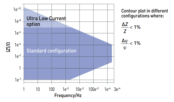
As a general rule, it is always better to keep the length of the connection leads as short as possible to reduce parasitic effects. This article on how to optimize the setup can provide further information. Additionally, it is also possible in EC-Lab® to measure and compensate the parasitic effects of the cable (see How to correct impedance measurements when using longer cables or a test fixture)
View BioLogic Dynamic EIS contour plots (Wolfram CDF player required)
Read More
Best Laboratory Practices Poster
Application notes
- AN#27 – Ohmic Drop: Part I: Effect on measurements
- AN#28 – Ohmic Drop: Part II: Introduction to Ohmic Drop measurement techniques
- AN#29 – Ohmic Drop Part III: Suitable use of the ZIR techniques?
- AN#44 – Artefacts in EIS measurements
- AN#48 – Inaccuracy of the corrosion current determination in presence of an ohmic drop: EC-Lab® solutions
Technical notes
- TN#13 – Long cell cables (updated October 11, 2010)
- TN#15 – Low current option: measurement precautions (updated June 7, 2010)
Tutorial
- Part IV – Experimental conditions


