

Safety & Conditional Limits: What are they and how are they used?
Latest updated: November 19, 2024BioLogic instruments (potentiostat / galvanostat and battery cyclers) are designed with embedded intelligence to improve the autonomy, efficiency, and accuracy of the instrument. Limits are part of the features fully managed by the instrument (not the computer). This prevents the experiment from being spoiled by a communication issue or a computer crash for example. In this way, the users are fully confident in the fact that their experiment will follow every step of the experimental procedure (conditional limits) or will be stopped if anything goes wrong (safety limits).
Another advantage of the limits being managed by the embedded hardware in the electrochemical device is that they are faster (delay between limit detection and action is shorter). The potentiostat or the battery cycler is capable of moving to another sequence or stopping the experiment itself without any delay as soon as the limit is reached. In battery application fields, for instance, it can prevent the battery from being overcharged.
What is the difference between “safety limits” and “conditional limits”?
Two kinds of limits are available in BioLogic software, EC-Lab® and BT-Lab®. They are the conditional limits and the safety limits. Let’s examine what their differences are and what they are designed for.
As said earlier, both are embedded in the hardware of the electrochemical instrument. Their principles are pretty much the same from a technical perspective. Their differences stand in the impact they have on the experiment once they are reached.
- Safety limit: The safety limits are designed to restrict the electrochemical instrument to values that are safe for the device under test. They are active for the whole protocol. The triggering of a safety limit always has the same effect on the electrochemical experiment. It opens the circuit and pauses the experiment. The user is warned that a safety limit has been reached via an error message (see Figure 1 below).

Figure 1: Example of error message appearing after a safety limit triggering.
Once the limit is triggered, no current can flow through the system. The system’s values are recorded every hour in the data file, but the current system’s values are available for the user in the status bar of the software in real time, as shown in Figure 2. The blue colored status bar indicates that the experiment is paused.

Figure 2: BT-Lab® status bar.
- Conditional limits: The conditional limits are part of the experimental protocol and are designed to make decisions during the experimental run. Once these limits are triggered the user may define a responsive action, e.g., go to a specific sequence (“Go to” or “next”) or end the experimental step. Thus, conditional limits bring intelligence to the progress of electrochemical experiments.
Depending on the technique used, a wide range of limits are available to fit every specific use.
To summarize, safety limits apply to the whole experimental protocol and are designed to protect the electrochemical cell or the battery from damage; conditional limits are used to build the experimental protocol and automate the sequences.
Where to find and use them?
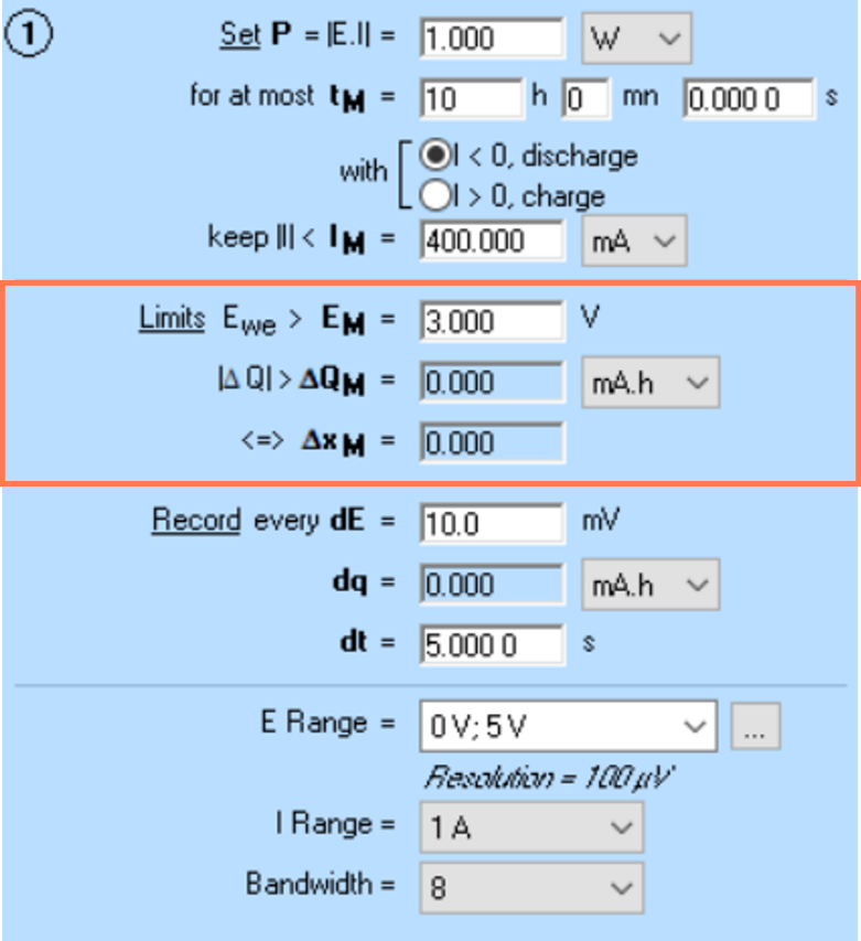
Safety limits can be found in the safety and advanced settings tab of EC-Lab® and BT-Lab® as shown in Figure 3.

Figure 3: Where to find the Safety limits on EC-Lab®.

The user can choose to delay the triggering of the safety limits by modifying the option “For t> XX ms”. The shortest delay is the timebase of the instrument (200 µs for EC-Lab® and 2 ms for BT-Lab®). For example, if $E_{WE}$ max = 5 V, and t > 100 ms, then the limit will be reached if $E_{WE}$ is greater than 5 V for longer than 100 ms. Once selected, an experiment limit is active during the whole experimental run.
As stated earlier, once a safety limit is reached, the experiment is paused. The pause allows the user to check the system and decide what to do next while the cell open-circuit mode, avoiding any risk of cell damage. If the user believes that it is safe to resume the experiment, they can simply click on the “resume” button and the experiment will continue where it left off. Otherwise, the user can completely stop the experiment.
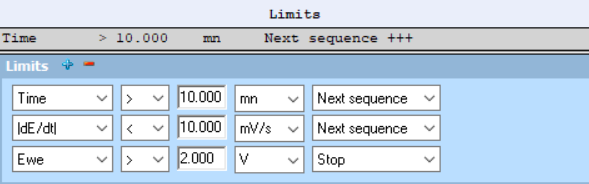
In most of the techniques available in BioLogic software, conditional limits are part of the technique parameters. The limits are adapted to the type of experiment performed by these techniques. They can be set as absolute values or as slopes. If several limits are available for one step, they work with the logical Boolean operator “or”. To ignore a limit, the user can set it equal to 0 as shown in Figure 4.

Figure 4: Where to find conditional limits on EC-Lab®.
CCCV cycling and Modulo Bat techniques limits.
CCCV cycling (CCCV) and Modulo Bat (MB) techniques are more flexible and allow the user to choose the limits they need. In the case of Modulo Bat, it is even possible to choose what to do next as described earlier in this article (see Figure 5).

Figure 5: Example of conditional limits for Modulo Bat experiment.
It is important to understand that the “Stop” option only applies to the technique. If the experiment is composed of several techniques (linked techniques) the experiment will move to the next technique if a limit is triggered. However, the Modulo Bat technique will be stopped, if for example, the voltage limit of Figure 5 is reached, then the instrument will not run the other sequences (lines) of the MB technique.
Slope calculation limits
Most of the time, optimizing the experiment duration is a key factor. But this need not be done at the expense of the quality of the measurements. Conditional limits based on slope calculations are typical examples of how potentiostats or battery cyclers can help the user to be more efficient.
For example, the user can decide to set a voltage slope limit $\left|\frac{dE}{dt}\right|$during an OCV period. This way, the user ensures that his system is not in a transient state and that the next step will begin as soon as the voltage is stable, without wasting time, as could be the case with a time limit.
Slope calculation is based on a proprietary adaptive algorithm which depends on the instrument’s specification technology, i.e., it is different for Premium potentiostats, Essential potentiostats and battery cyclers, because they each have a different timebase. The algorithm determines the frequency at which the limit will be checked and is necessary to avoid any false positives triggering the limit. In other words, for a fast slope, the limit will be checked very regularly, so the limit trigger will happen quickly, but for a slower slope, it will be slower. Table 1 shows examples of different slope rates (dE/dt) and the frequency of the check for Premium range instruments.
Table 1: Example of slopes and their corresponding frequency of limit check.
| Slope limit | Time after which the limit is tested |
| 0.001 mV/h | 5,657 s |
| 1 mV/h | 56 s |
| 3,600 mV/h | 0.24 s |
For a typical slope in voltage of 1 mV/h, the hardware will check the limit after 56 s.
Battery cutoff voltage
The cutoff voltages define the voltage range allowed for the battery without being irreversibly damaged. It can stop the constant current step of a charge or discharge sequence. It is used in Galvanostatic Cycling with Potential Limitation (GCPL), CCCV cycling (CCCV) and Modulo Bat techniques for example.
The cutoff voltage is processed across 10 points. The delay between the first detection and the action is 10 times the time base i.e., 2 ms for Potentiostat and 20 ms for the battery cyclers. Thanks to the embedded hardware, it is not dependent on the sampling rate, those 10 points are only dependent on the timebase of the instrument. This way, the user is assured that the voltage limit is reached because of the actual state of the device under test (battery, supercapacitor, …) and not because of any noise the instrument observes.


