

A comprehensive solution to address battery module/pack Energy Storage – Application Note 59
Latest updated: January 31, 2024In this context, BioLogic is offering a full solution to address this need. In this application note, the connection of the pack to the instruments and the software settings are described. The data of the cycling are briefly discussed.
Introduction
To address high power applications, such as Electric Vehicles (EVs) or Hybrid EVs. Battery modules or packs (Fig. 1) are studied intensively, especially the behavior of the individual element within the pack.
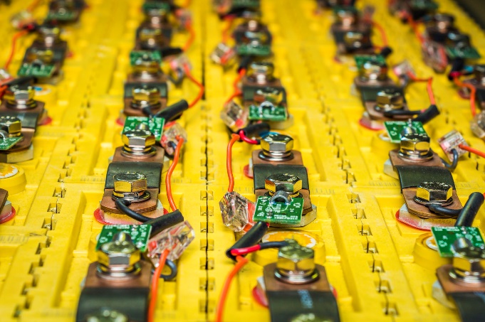
Figure 1: Battery pack.
To better manage the pack, simultaneous measurements of the whole pack and the elements within the pack are required. These data are of interest to develop appropriate algorithms to feed the Battery Management system (BMS) [2-3].
In his context, BioLogic is expanding their solution for stack applications [1] and is offering a full solution to address this need. In this application note, the connection of the pack to the instruments and the software settings are described. The data of the cycling are briefly discussed.
EXPERIMENTAL SET-UP
MEASURING HARDWARE
To perform such experiment, the following instruments and options are required (Fig. 2):
- VMP3 – It is a potentiostat/galvanostat that is used to control and record the data simultaneously.
- Booster (here a FlexP 0160 booster is used) – It is connected to one of the channels of the VMP3 potentiostat/galvanostat. It manages the power of the pack.
- SAM-50 (Sense Adapter Module) – It is connected to additional channels. They measure the individual element in series within the pack.
One SAM-50 is connected to 5 channel and can manage up to 10 elements. Up to 3 SAM-50 can be linked together to measure up to 30 additional voltages. This option is only compatible with VSP-3e, VMP-3e, VMP3 and MPG2 [4].
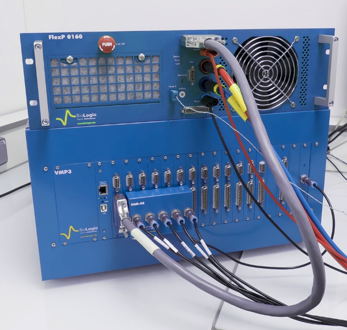
Figure 2 Hardware setup. VMP3 connected to the Current/voltage booster (FlexP 0160) on the top and SAM-50 plugged onto the VMP3 front pane
EC-Lab® settings
The measurement of the element with the pack has to be activated EC-Lab® software. It is the so-called, “stack” mode, and is available in the “Edit” menu, select the “Group/Synch/Stack/Bipot”frame.
The window in Fig. 3 will pop up. For the pack of interest, 10 branches are measured and the SAM-50 is plugged onto the channels 2 to 6 of the VMP3. Check the boxes 2 to 6 in the pop up window as shown in Fig. 3. Channel 1 is connected to the FlexP 0160, it is the “Stack master” (Fig. 3).

Figure 3 Stack window in EC-Lab®.
The cycling is performed at the maximal regime of the pack i.e. 30 A (pack specifications are given in the battery pack section) with ModuloBat (MB) technique (Fig. 4) between 42.5 V and 37.0 V. Each cycle is followed by one EIS measurement in galvanostatic mode (GEIS, Fig. 5) [5].
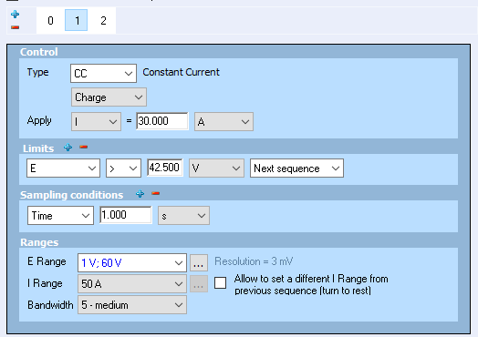
Figure 4 Cycling settings (ModuloBat technique).
Galvano EIS is performed at 5 A between 10 kHz and 100 mHz.
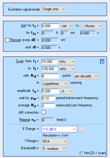
Figure 5 EIS settings (Galvano EIS technique).
The battery pack
The battery pack under test is custom made based on LFP cells (K226650E01). It is a 12S10P (120 cells) configuration (Fig. 6).
The specifications are:
- Capacity: 32 A·h
- Max charge/discharge: 30 A
- Nominal voltage: 38.4 V
- Max voltage: 43.8 V
- Min voltage: 32.0 V
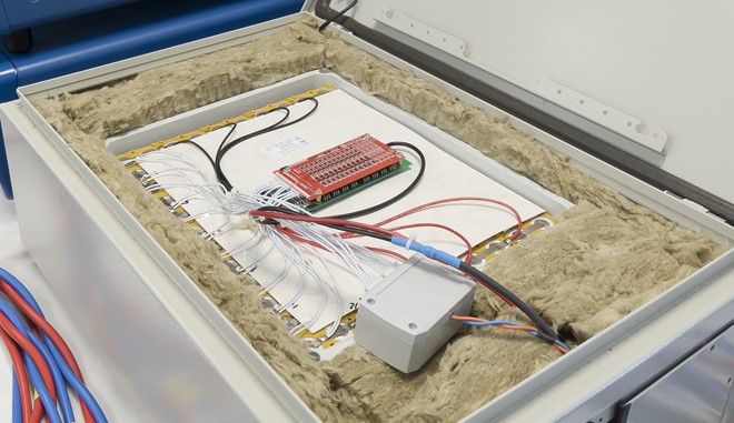
Figure 6 Battery pack under test.
The connection to the battery pack
The FlexP-0160 is connected to the battery pack in two electrode configuration mode i.e. red wire to the positive side and blue wire to the negative side (Fig. 7).
SAM-50 is connected directly to the element E1, E2, to En (Fig. 7). A schematic appears in EC-Lab® to help the customer to connect appropriately the SAM-50 (Fig. 7) and in the application note #16 [1].
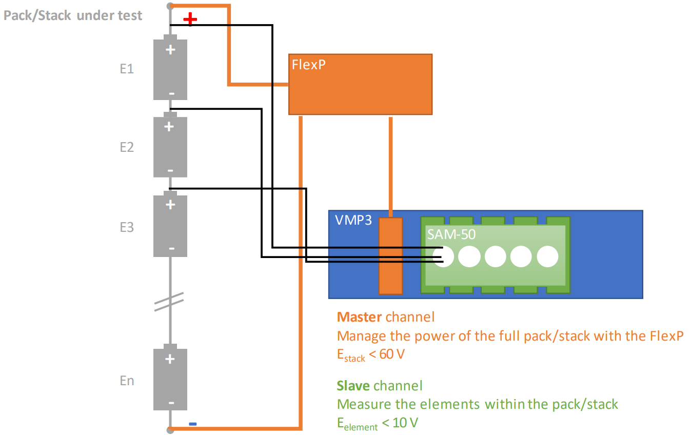
Figure 7 Scheme of the set up connection.
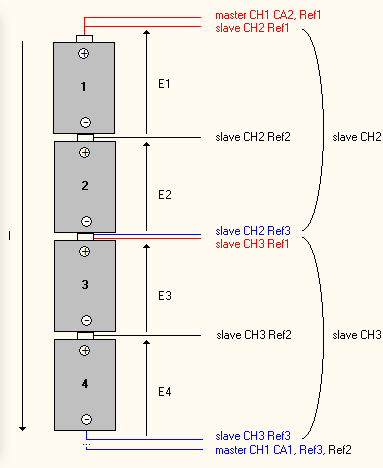
Figure 8 Scheme of the SAM-50 connection to the battery pack.
Safety considerations
It is a high-energy device so safety precautions have to be applied.
- Personal Protective Equipment (PPE) must be used such as gloves and mask.
- IP2X connectors are mandatory. Connect the cable to the booster first and then to the battery pack.
- Safety limit in EC-Lab® has to be set appropriately (Fig. 9). It is highly recommended to set the voltage range, maximum current and maximum temperature.
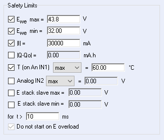
Figure 9 Safety limits in Advanced Settings.
NOTE: FlexP-0160 includes a K-type thermocouple that manages the temperature recording. This option is automatically set in EC-Lab® (Fig. 10).
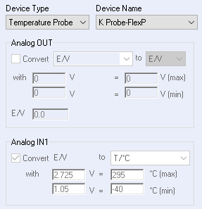
Figure 10 Temperature settings in the External device tab.
Data discussion
The resulting data of the full pack (named “stack”) and the data from the individual elements (numbering of the element is added) are automatically displayed in EC-Lab®. For example, EStack is the voltage of the whole stack whereas E1 is the voltage of the element #1.
The cycling data (Fig. 11) are slightly different, but the difference of the EIS data is much more significant (Fig. 12), especially for the element #4.
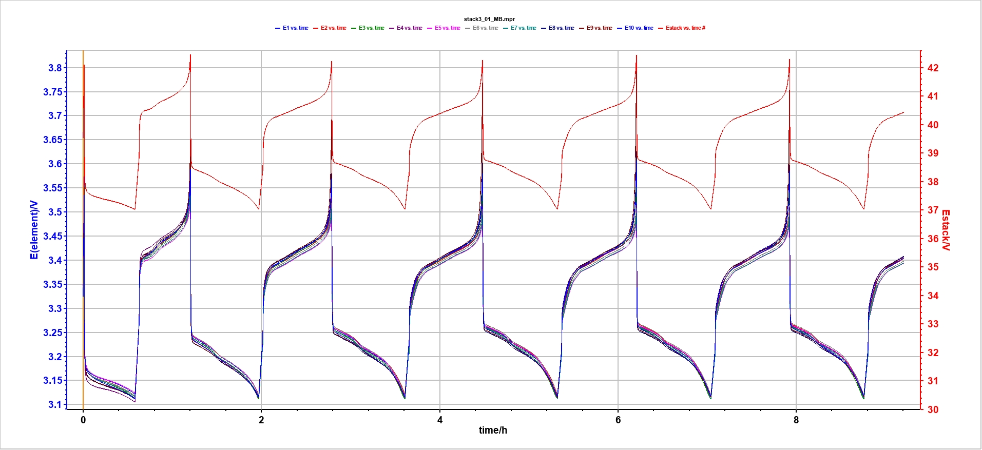
Figure 11 Cycling data at +/-30 A. Voltage changes of the stack in red and the individual element are displayed in other colors.
This wide frequency allows us to characterize the internal resistance (above 1 kHz) and the diffusion process of the pack and the individual elements (below 1 Hz).
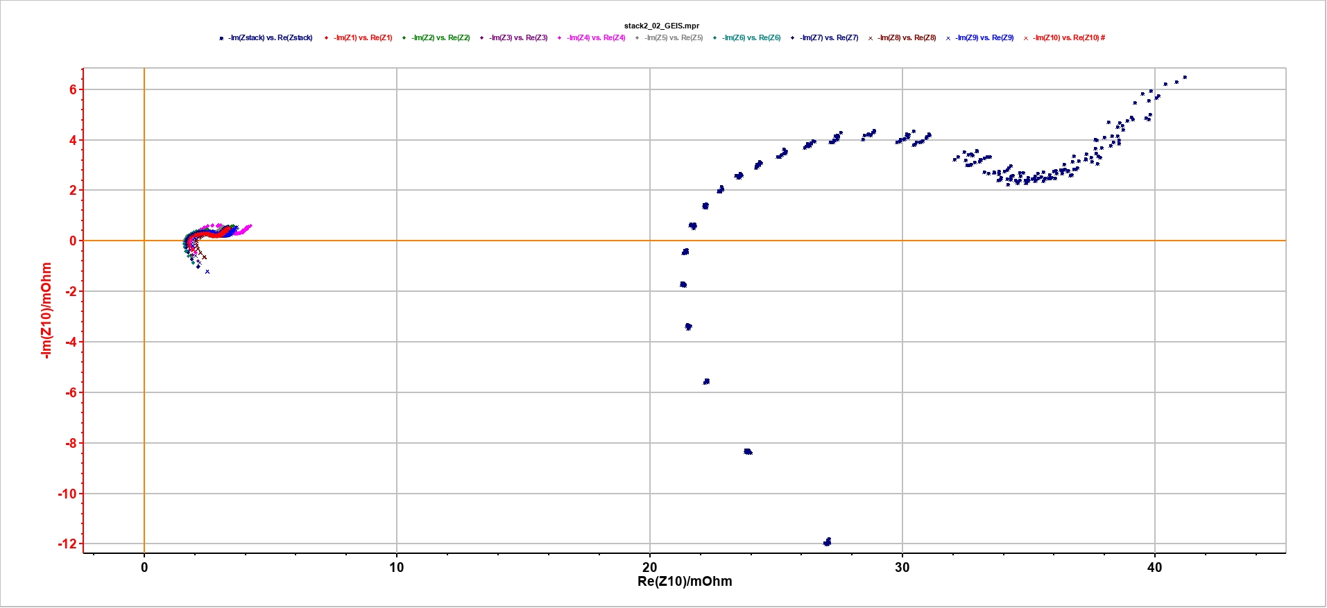
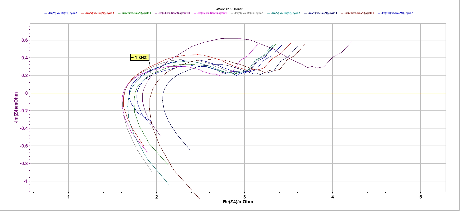
Figure 12 EIS data. Top: stack and individual element data. Bottom: zoom on the individual element EIS data. Frequency at 1 kHz is displayed.
The resulting data can be analyzed by any analysis and process tool available in EC-Lab®, for example ZFit for EIS data fitting.
It is also easy to select only the elements of interest by clicking on the “Stack” button available in the “File Selection” window.
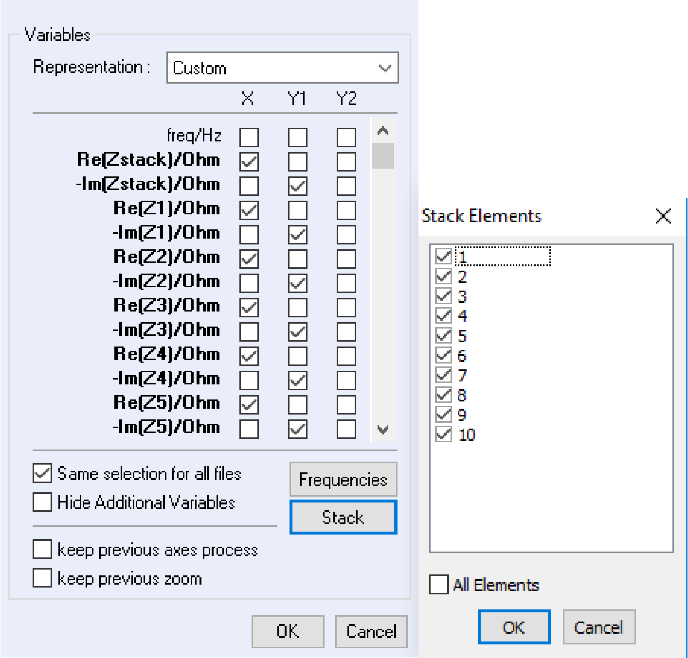
Figure 13 Stack elements selection in the Selector.
Conclusion
This application note shows how to set up a measurement on a battery pack where the voltage of the element in series of the pack is measured. This raw data show that each cell exhibits different result, specifically for EIS data. The algorithm of the BMS has to take into account this difference to better manage the battery pack and then improve its lifetime.
The same measurements are possible with supercapacitor or fuel cell pack/stack.
References
- Application Note #16, Simultaneous impedance measurements elements of a running cell stack in EC-Lab Express
- G. L. Plett, Advanced Materials and Methods for Lithium-Ion Batteries(2007).
- G. L. Plett, Journal of Power Sources 134 (2004) 252.
- Technical Note #27, Stack Measurements with SAM-50 modules
- Application Note #49, Potentio or Galvano EIS
Revised in 03/2023


