

The Gerischer Impedance
Latest updated: November 19, 2024Introduction
Three Gerischer impedance elements (classical Gerischer, modified Gerischer 1 and 2) are available in EC-Lab®. Which specific electrochemical process is modelled by the Gerischer impedance? In which applications can it be found to accurately describe the electrochemical mechanism that is at stake? This article will provide clear answers to these questions.
Why Gerischer ?
The Gerischer impedance derives its name from Heinz Gerischer (1919 – 1994), a German electrochemist who worked on electrode kinetics, semiconductor electrochemistry and even designed a potentiostat to study fast electron processes [1]. One of his earliest papers, which would subsequently be the reason why his name was given for an impedance expression and element was titled “Alternating-Current Polarization of Electrodes with a Potential-determining Step for Equilibrium Potential” [2]. He is the first to express the concentration impedance related to an electrochemical mechanism which consists of a heterogeneous redox E reaction at the electrode|electrolyte interface followed or preceded by a homogeneous bulk chemical reaction C.
Theoretical description
Let us consider the following electrochemical two-step EC electrochemical reaction:
The redox reaction E here shown in the reduction direction with the standard rate constant $k°$ where the oxidizing species $\text O$ is reduced to $\text R$:
$$\text O + n \text e^- \leftrightarrow \text R\tag{1}$$
The chemical homogeneous reaction C, transforms $\text R$ into $\text Y$ following the homogeneous reaction with the forward rate constant $k_\text f$:
$$\text O \; \xrightarrow{k_\text f} \text Y\tag{2}$$
The Faradaic impedance of such an electrochemical process is composed of a charge transfer resistance $R_\text {ct}$ and a concentration impedance, which in this case is a Gerischer impedance $Z_\text G$ whose expression is the following:
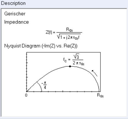
$$Z_\text G(p)=\frac{R_\text G}{\sqrt{1+\tau_\text G p}}\tag{3}$$
with $ R_\text G$ and $\tau_\text G $, the Gerischer resistance and time constant in $\Omega$ and $\text s$, respectively, and $p=2\pi jf$, where $f$ is the frequency in Hz.
The typical shape of the Gerischer impedance is given in the ZFit/ZSim circuit editing tool available in EC-Lab®, when choosing the G element (Figure 1). The expression of the characteristic frequency which corresponds to the extremum of the imaginary part of the impedance is also given in Figure 1.
Please note that EC and CE mechanisms are identically modelled by the Gerischer impedance.

Figure 1: Expression and Nyquist representation of the Gerischer impedance.
Heinz Gerischer, in his seminal paper [2], focused on the reaction occurring on a flat or hemispherical electrode in a quiescent electrolyte under semi-infinite diffusion. Nineteen years later, Sluyters-Rehbach and Sluyters [3] presented the general impedance expression for the CE reaction, where the E reaction is preceded by an homogeneous chemical reaction. Twenty years later, Levart and Schuhmann [4] developed a model for the convective diffusion impedance of a disk electrode in the presence of a homogeneous chemical reaction. The full kinetic study can be found in the works by Harding et al. [5], and Montella et al. [6], more than sixty years after the initial paper by Gerischer.
The kinetics and Faradaic impedance of the redox reaction under diffusion-convection conditions are described in Application notes 56 and 66. In Gerischer conditions, the interfacial concentration of electroactive species is not only controlled by mass transport and electronic charge transfer but also by the partial reaction rates of the homogeneous chemical reaction. Taking as examples Eq. 1) and 2) the interfacial concentration of $\text O$ will depend on the forward reaction rate $k_\text f$ of the homogeneous reaction.
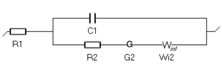
Figure 2 is an animated figure which shows the influence of the increase of the electron transfer rate constant. The orange curve shows the impedance of the electrode, that is to say the Faradaic impedance, shown in blue, with a capacitor in parallel. The corresponding equivalent circuit is shown in Figure 3.
As the charge transfer rate increases, the charge transfer resistance becomes negligible compared to the Gerischer impedance (arc in the middle) and the diffusion-convection impedance (low-frequency arc). The red dot corresponds to the Gerischer characteristic frequency, as shown in Figure 1.

Figure 2: Nyquist representation of the Faradaic impedance (blue line) and the electrode impedance (orange line) for an EC/CE reaction occurring at a rotating disk electrode ($\Omega$=2300 RPM) and for various $k°$. The red dot represents the Gerischer characteristic frequency.


Figure 3: Equivalent Circuit Model corresponding to the electrode impedance shown in Fig. 2.
Most of the information given here is also accessible interactively through a Wolfram Demonstration. To play the demonstration you need to download and install Wolfram demonstration player, which is free and available here.
Applications
The Gerischer impedance is most frequently used to explain electrochemical mechanisms occurring in solid state electrochemistry, where solid conductors and porous electrodes are involved e.g. gas-diffusion electrodes in fuel cells and air-batteries, and photoelectrodes.
Fuel cells
Solid oxide fuel cells
The Gerischer impedance is used to model the impedance behaviour of a mixed ionic electronic conductor (MIEC) where $\text O_2$ in the gas phase is reduced at the MIEC|gas|current-collector triple interface in $\text O^{2-}$, consuming electrons from the collector, then diffuses through the MIEC to the electrolyte phase [7-10]. The chemical reaction that “justifies” the Gerischer impedance is the exchange of oxygen between the gas phase and the MIEC [7].
Figure 4 schematically depicts the ALS mechanism first proposed by Adler, Lane and Steele to describe the $\text O_2$ transport and reduction and the “triple interface” mechanism involved: i) $\text O_2$ exchange at the gas phase|MIEC interface, ii) electronic charge transfer at the current collector|MIEC interface, iii) ionic charge transfer via oxygen vacancies at the MIEC|electrolyte interface [7].

Figure 4: Schematic representation of the reaction mechanism considered in the ALS model. Image adapted from [7].

Some authors used a modified Gerischer impedance expression with a dispersion parameter $\alpha$, accounting for a “fractal” nature of the porous electrode [11-12].
The ad hoc modified Gerischer impedance element Ga1 is available in ZSim/ZFit and its expression and shape are shown in Fig. 5.

Figure 5: Expression and Nyquist representation of the modified Gerischer impedance 1.
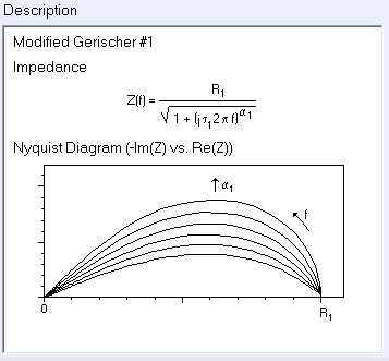
This element Ga1 is a particular case of the Havriliak-Negami impedance [13] used to describe the complex dielectric behavior of the $\alpha$-dispersions of polymers.
Proton exchange membranes fuel cells
Gerischer impedance is used in PEMFC to model “the reversible adsorption reaction of hydrogen to carbon black along the pore walls and the subsequent diffusion along the surface to the catalyst” [14], occurring on the anode side of the PEMFC.
Metal-air batteries
Metal air batteries, more specifically Li-air batteries, employ porous electrodes in which $\text O_2$ diffuses to be reduced by electrons produced by Li oxidation on the anode side of the battery. Similar to fuel cells, this diffusion-reaction at equilibrium is modeled by a Gerischer or modified Gerischer impedance [15].
Photovoltaics
Bisquert [16-17] was one of the first to present the Gerischer impedance as a way to model diffusion-recombination of photoexcited electrons occurring in systems such as porous $\text {TiO}_2$ photoelectrodes, specifically when the recombination time is much shorter than the diffusion time across the material layer.
Transmission lines
It must be pointed out that the Gerischer impedance is equivalent to the semi-infinite uniform distributed R+R/C (URRC) transmission line impedance [18] (Fig. 6).

Figure 6: Semi-infinite short-circuited uniform distributed RRC (URRC) transmission line.
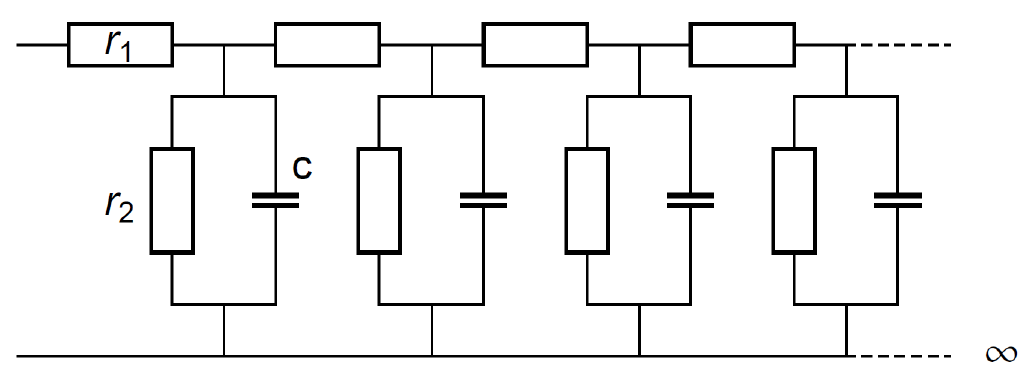
The impedance of this transmission line is:
$$Z_\text {URRC} \equiv \frac{\sqrt{r_1 r_2}}{\sqrt{1+r_2 c j \omega}}\tag{4}$$
Which is equivalent to the Gerischer impedance shown in Fig. 1 with $R_{\text G_1}=\sqrt{r_1 r_2}$ and $\tau_{\text G_1}=r_2 c$.
Conclusions
Although originally developed to described EC/CE reaction in aqueous electrolytes, the Gerischer impedance is mainly used in solid state ionics and solid state electrochemistry, specifically in applications where gas phases are involved such as fuel cells. Effectively in fuel cells “OER mechanism as a solid-state diffusion, followed by a pure chemical reaction of oxygen exchange with the ambient atmosphere […] results in a Gerischer-type element impedance under semi-infinite condition” [19].
Modified Gerischer impedances are also used to model complex dielectric behaviours of polymers and in this sense are related to the Havriliak-Negami impedance.
Finally, it can be used to fit transmission lines impedances.
References
[1] A. Heller, D. Kolb, and K. Rajeshwar, “The life and work of Heinz Gerischer”, The Electrochemical Society Interface, Fall 2010
[2] H. Gerischer, “Wechselstrompolarisation von elektroden mit einem potentialbestimmenden schritt beim gleichgewichtspotential I.”, Z. Phys. Chem., vol. 198, no. 1, p. 286, 1951.
[3] M. Sluyters-Rehbach, J.H. Sluyters, in: A.J. Bard (Ed.), Electrochemical Chemistry, vol. 4, Marcel Dekker, New York, 1970, p. 68.
[4] E. Levart and D. Schuhmann, « Sur la détermination générale de l’impédance de concentration (diffusion convective et réaction chimique) pour une électrode à disque tournant” J. Electroanal. Chem., vol. 53, p. 77, 1974.
[5] M. S. Harding, B. Tribollet, V. Vivier, and M. E. Orazem, “The influence of homogeneous reactions on the impedance response of a rotating disk electrode” J. Electrochem. Soc., vol. 164, p. E3418, 2017.
[6] C. Montella and J.-P. Diard, « Etude de réactions électrochimiques par SIE. Réactions (EC/CE) ».
[7] S. B. Adler, J. A. Lane, and B. C. H. Steele, “Electrode kinetics of porous mixed-conducting oxygen electrodes” J. Electrochem. Soc., vol. 143, p. 3554, 1996.
[8] J.-S. Kim, S.I. Pyun, “A review of AC-impedance models for the analysis of the oxygen reduction reaction on the porous cathode for solid oxide fuel cell” J. Korean Electrochem. Soc., vol. 8, p. 106, 2005
[9] A. Flura, C. Nicollet, V. Vibhu, B. Zeimetz, A. Rougier, J.-M. Bassat, and J.-C. Grenier, “Application of the Adler-Lane-Steele Model to Porous La2NiO4+δ SOFC Cathode: Influence of Interfaces with Gadolinia Doped Ceria” J. Electrochem. Soc., vol. 163, p. F523, 2016.
[10] L. Yasin, A. Atkinson, S. J. Cooper, A. Bertei, “Identifiability of the mechanisms governing the reaction kinetics of MIEC electrodes in solid oxide cells” Electrochim. Acta, vol. 472, p. 143418, 2023.
[11] H. Wang, K. J. Yakal-Kremski, T. Yeh, G. M. Rupp, A. Limbeck, Jürgen Fleig and S. A. Barnett, “Mechanisms of Performance Degradation of (La,Sr)(Co,Fe)O3-δ Solid Oxide Fuel Cell Cathodes” J. Electrochem. Soc., 163 p. F581, 2016.
[12] P. Costamagna, E. M. Sala, W. Zhang, M. L. Traulsen and P. Holtappels “Electrochemical impedance spectroscopy of La0.6Sr0.4Co0.2Fe0.8O3-δ nanofiber cathodes for intermediate temperature – Solid oxide fuel cell applications: A case study for the ‘depressed’ or ‘fractal’ Gerischer element” Electrochim. Acta, 319 p. 657, 2019.
[13] S. Havriliak and S. Negami “A complex plane analysis of $\alpha$-dispersions in some polymer systems” J. Polymer Sci. C, 14 p. 99, 1966.
[14] A.-K. Meland, D. Bedeaux, and S. Kjelstrup “A Gerischer phase element in the impedance diagram of the polymer electrolyte membrane fuel cell anode” J. Phys. Chem. B, 109 p. 21380, 2005.
[15] M. Mehta, G. Mixon, J .P. Zheng, and P. Andreia “Analytical electrochemical impedance modeling of Li-Air batteries under D.C. discharge” J. Electrochem. Soc., 160 p. A2033, 2013.
[16] J. Bisquert “Theory of the impedance of electron diffusion and recombination in a thin layer” J. Phys. Chem. B, 106 p. 325, 2002.
[17] J. Bisquert, I. Mora-Sero, and F. Fabregat-Santiago “Diffusion–recombination impedance model for solar cells with disorder and nonlinear recombination” ChemElectroChem, 1 p. 289, 2014.
[18] Biologic Application Note 43 “How to fit transmission lines with ZFit”
[19] E. Effori, J. Laurencin, V. Tezyk, C. Montella, L. Dessemond, E. Siebert « A physically-based modelling to predict the cyclic voltammetry response of LSCF-type electrodes : impact of the ohmic losses and microstructure. Solid State Ionics, 371 p. 115765, 2021.


