

The different current and voltage setpoint options in EC/BT-Lab®
Latest updated: November 18, 2024A potentiostat/galvanostat is an instrument capable of applying a voltage or current to a cell for a specific application. But depending on the choice of an absolute or relative setpoint, the setpoint value will not be calculated in the same way. This article presents the different options available using EC/BT-Lab® software.
Voltage setpoint options
EC-Lab® and BT-Lab® software allow the user to choose how voltage or current setpoints are defined. As can be seen in Fig. 1, four options are available for the applied voltage.

Figure 1: Voltage setpoint options available.
1.Ref
This means that the applied voltage value is the voltage value between the working electrode potential and the reference electrode potential.
If I set Ei = 2 V vs. Ref, then Ewe = 2 V.
2.Eoc
This means the applied voltage value is applied relatively to the OCV value, measured just before the experiment.
If the OCV is -0.5 V and I set Ei = 2 V vs. Eoc, then Ewe = 2 – 0.5 = 1.5 V.
3. Ectrl
This means that the applied voltage value is applied relative to the last voltage value controlled in an amperometric (or voltage-controlled) technique preceding the technique of interest.
If the preceding technique was based on Cyclic Voltammetry and the last applied voltage Ewe was 1.5 V, if I set Ei = -0.5 V vs. Ectrl, the applied voltage Ewe = -0.5 + 1.5 = 1 V
4. Emeas
This means that the applied voltage value is applied relative to the last voltage value measured in a potentiometric (or current-controlled) technique before the considered technique, for example, CC (Constant Current) technique followed by a CV (Constant Voltage) technique.
If the last measured value during the CC technique is 0.832 V and I set Ei = 0 V vs. Emeas for the CV technique then the value applied is Ewe = 0.832 V.
Current setpoint options
As can be seen in Fig. 2, there are three options for the current setpoint.

Figure 2: Current setpoint options available.
1. None
The “none” option is the default and the most commonly used one: the current is set to the value specified in the settings.
2. lctrl
This means that the current value is defined relative to the last controlled current value of a potentiometric (or current-controlled) technique, preceding the considered technique.
If the preceding technique is a galvanodynamic technique (or current scan) and the last controlled current value is -100 µA, if I set Is = 50 µA vs. Ictrl, the applied current is = 50 – 100 = -50 µA.
3. lmeas
This means that the current value is defined relative to the last measured current value of an amperometric (or voltage-controlled) technique, preceding the considered technique.
If the preceding technique used a potentiodynamic technique (or voltage scan) technique and the last measured current value is 951 nA, if I set Is = 50 µA vs. Imeas, the applied current is = 50 + 0.951 = -50.951 µA.
Real application examples
Eoc
Applying a voltage relative to Eoc is relevant for EIS measurements on a battery, as it allows users to easily perform the measurement without applying a DC offset voltage to the cell (Figure 3). A DC offset voltage would produce a DC current and non-steady-state conditions of the system.
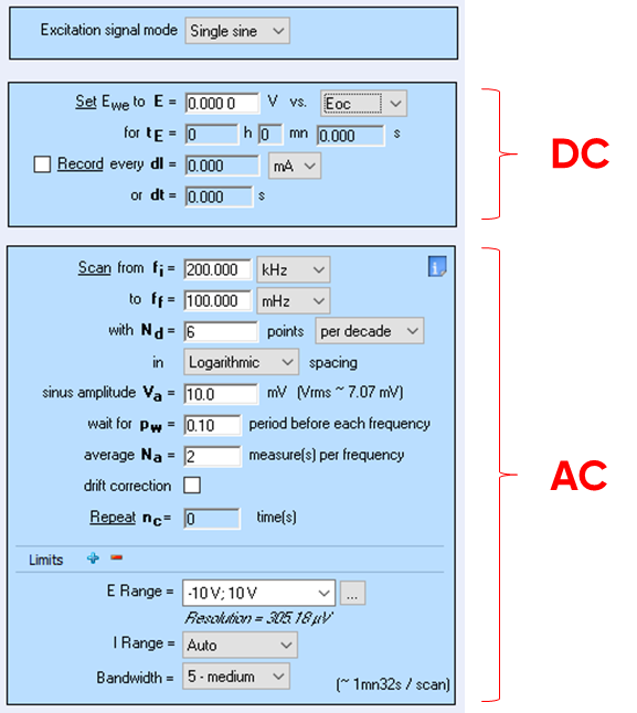
Figure 3: An EIS experiment using the “Eoc” option.
Another example: during CV experiments, if the initial voltage is applied vs. “Eref” instead of vs. “Eoc”, a current peak can be observed due to the voltage gap between “Eoc” and the initial applied voltage.
Emeas
CC-CV (Constant Current-Constant Voltage) experiments are good examples for the “Emeas” option. This is commonly used in the CV technique, after the CC technique in order to maintain the cut-off voltage (Fig. 4).

Figure 4: CV step of a Modulo Bat technique using the vs. Emeas option
Ictrl / Ectrl
“Ictrl” and “Ectrl” are mainly used for pulse experiments. In the following example, “Ictrl” is used to make 10 steps of 10 seconds with an increment of 10 mA between each one, starting from 0 mA and ending at 100 mA (Fig. 5).


Figure 5: Use of the”Ictrl” setpoint option to easily set up pulse experiments using sequences.
When multiple techniques are linked, it is possible to add an OCV step between each technique using the appropriate checkbox (Fig. 6). This is mandatory when several Iranges are needed over a range of linked techniques.
This functionality allows the potentiostat to return to OCV, but is not used to redefine the OCV value used as a reference point for the “vs. Eoc” setpoint. To do so, an OCV or rest sequence/technique has to be directly added before the relevant sequence or linked technique.


