

FlexP + Water Cooling = More power (up to 800 A)!
Latest updated: November 15, 2024How FlexP boosters address a critical high-power testing need for EVs & other high-power applications…and understanding heat dissipation
Renewable energy sources and storage are two key modern-day challenges. With the emergence of electric or fuel-cell-powered vehicles, a critical need for high-power energy solutions now exists. The FlexP booster series, with its advanced capabilities, including accuracy, and precision, for both DC and EIS measurements, clearly addresses this need. The FlexP0012 (12 V / 200 A) targets electrolyzer, fuel cell, and large cell characterization applications, whereas the FlexP0060 (60 V / 50 A) is more appropriate for battery packs.
FlexP: A true high-power EV/high-power test solution
From a technological perspective, one of the key challenges in designing an instrument able to manage high levels of power is power dissipation. This article is primarily concerned with heat dissipation in medium power systems (below 1 kW). BioLogic FlexPs are compact systems, that only take 3 rack units per booster inside a 19” cabinet. Air cooling is in fact possible with the FlexP, but water cooling enables truly high-power use. In fact, only half of the 2.4 kW capabilities of the FlexP are dissipated by air cooling and the rest is achieved by liquid cooling when required. The compact footprint of the boosters, however, is a true advantage…
Water cooling = More Power! How compact boosters means more power…
BioLogic made a conscious, and pragmatic choice when adopting a water cooling system for the FlexP booster series. By using water cooling systems, the footprint of the booster design was able to be significantly reduced. And this compactivity, enables, in practical terms, several boosters to be linked together in parallel (up to 4, for up to 800 A) resulting in a truly high-power solution.
![]()
Figure 1: Two FlexP-0012 inside a 19” cabinet (6 rack-units high)
Heat dissipation calculation
From a technologic perspective, the amount of heat generated by the instrument differs depending on the control mode used and the FlexP specifications (Umax FlexP and UMin FlexP):
- During charge experiments (positive current), the power that is not flowing through the cell is directly dissipated as a joule effect by the heat sink. Example: applying +195 A to produce hydrogen, at 1 V (electrolyzer mode).
- During discharge experiments (negative current), the power that is delivered by the cell is directly dissipated by the heat sink. Example: applying -150 A to a fuel cell at 0.9 V.
Considering these examples, liquid cooling will be used at a positive current (> 1200 W), while it will not be in fuel cell mode (< 1200 W).
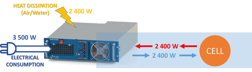
Figure 2: the relationship between electrical consumption, available power, and heat dissipation
The operating area graphs below are useful as they allow you to quickly and easily check which experiments require, or do not require, liquid cooling. It is also possible to check if the intended experiment can be performed using the booster, avoiding power supply or heat dissipation issues. Figure n°3 represents the operating area graph of a FlexP-0012 booster. In orange, you can see the area that only requires air-cooling, and in blue, the one which requires the addition of a liquid cooling system.
The bottom left (minimum negative voltage and maximum negative current) and the top right corners (maximum positive voltage and maximum positive current) in the operating area are not limited by heat dissipation but by power supply limitations.
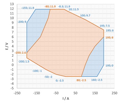
Figure 3: FlexP-0012 operating area.
Tech-tips for liquid cooling management and the FlexP Boosters
What type of systems can be used for liquid cooling? Can I use tap water?
- Multiple types of systems or tap water can be used. The following two conditions must be fulfilled: the flow rate must be at least 2 L/min per FlexP, at a temperature of 20°C. Chillers are also compatible with this need.
How to connect the liquid cooling system to the FlexP?
- Two 6 mm quick connect connectors are available at the rear of the FlexP boosters. 6 mm OD PFA tubes can directly be pushed inside the connectors, and you’re good to go (leak-free).
Are there any precautions to take when using a chiller?
- A discharge circuit must be added to allow the liquid to flow back to the chiller if liquid cooling is not required, to prevent pump damage. A proportional valve and a manometer are placed on the discharge circuit to control and monitor the pressure inside the whole system: this ensures that the flow rate is adequate (Figure 3).
- We recommend using a mixture of water and glycol ethylene in a ratio of 70 % / 30 % for liquid cooling, to avoid corrosion and algae formation inside the internal pipes.
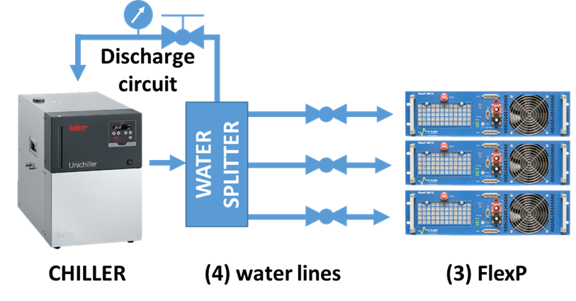
Figure 3: Simplified schematic of the liquid cooling system for FlexPs
How does liquid cooling kick in, in practical terms?
- A solenoid valve opens or closes the liquid flow. Its aim is to cool down the electronics to prevent overheat, but also to prevent water condensation when liquid cooling is not required.
Please contact your sales representative for questions about system compatibilities and/or operating pressure values.
More information
The FlexP-0060 also can switch the voltage capabilities of the booster from 60 V to 24 V. In this configuration, the FlexP-0060 has to dissipate less than 1.2 kW, so liquid cooling is not required.


