

Introduction to Foil Cell Scanning Probes – Application Note 20
Latest updated: June 17, 2024Abstract
The Foil Cell is an optional accessory for use with the µTriCell and Shallow µTriCell. It has been designed specifically for use with flat, foil type electrodes, such as those used in batteries. This note demonstrates the use of the foil cell with two different sample types: (1) a polycarbonate membrane, (2) commercial battery electrodes.
Introduction
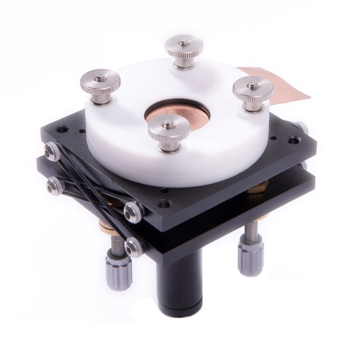
The Foil Cell (Part Number: U-uFoilCell), Fig. 1, is an optional accessory for the µTriCell and Shallow µTriCell used with the M370 and M470. It has been designed specifically for use with thin, flat samples, in particular the foil electrodes often used in battery research. Unlike the µTriCell options the Foil Cell allows the user to seal directly on to the sample of interest without the need for any extra components. Furthermore this has been achieved to use a minimal amount of electrolyte, whilst not compromising the user’s ability to position the probe with respect to the sample, or perform subsequent experiments.

Figure 1: The Foil Cell (U-uFoilCell) allows the measurement of flat, foil type samples.
This application note aims to introduce the Foil Cell through the demonstration of its use with two different sample types, a polycarbonate membrane, and commercial battery electrodes.
Advantages Of The Foil Cell
The Foil Cell allows advantages for the user over traditional cell configurations for a number of reasons. When using the Foil Cell, it is not necessary to adhere the sample onto the base of the cell. This is advantageous for samples which are not easily adhered by normal means, for example because they will easily be contaminated by the adhesive, or because the adhesive is not chemically compatible with the electrolyte of interest. Furthermore by removing the need to adhere the sample the setup time for the experiment can be noticeably reduced for the user. By sealing the cell directly on to the sample of interest it also ensures that, unlike in traditional setups, the edges of the sample are not exposed to the electrolyte. This rules out any detrimental effect the edge may have on the measurements performed, and ensures the user is not measuring an edge effect. Finally, the reduced electrolyte volume required by the Foil Cell is advantageous when users are working with expensive electrolytes.
Using The Foil Cell
The Foil Cell is an optional accessory which mounts directly to the base plate of the (Shallow) µTriCell. It is composed of a top and bottom PTFE half. During use the sample rests directly on the bottom PTFE half, while the top PTFE half seals to the sample through the use of the sample sealing O-ring. This half has a gradual recess allowing the user to view the probe positioning with respect to the sample using the VCam, Fig. 2.
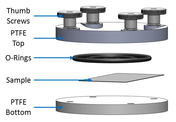
To use the Foil Cell the user should mount the bottom PTFE half onto the baseplate of the (shallow) µTriCell, before mounting this onto the M370/470 base. This should then be levelled before placing the sample onto the bottom PTFE half. The top PTFE half should be placed on top, again ensuring the sample is central to the cell opening. Finally all components are held in place by tightening the finger screws. An exploded view of the complete Foil Cell is shown in Fig. 3.

Figure 2: The gradient of the Foil Cell allows the VCam to be angled to position the probe with respect to the sample.
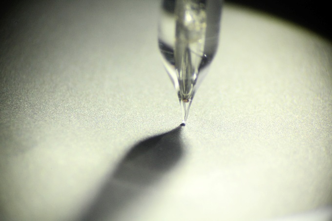

Figure 3: An exploded view of the Foil Cell is shown.
While every endeavour has been made to make the Foil Cell relevant to use in battery measurements it is advised that users always ensure the chemical compatibility of all components before proceeding with any measurements.
Results
Membrane
Using the M470+3300 A Whatman® CycloporeTM track etched polycarbonate membrane with 12 µm pores (PC12) mounted on top of a piece of copper tape was measured using the Foil Cell. The copper tape was mounted so a length extended out of the Foil Cell allowing electrical contact to easily be made. SECM area scan measurements were performed in 2.5 x 10⁻³ mol/L K3[Fe(CN)6]/ K4[Fe(CN)6] in 100 x 10-3 mol/L KCl using a 10 µm Pt Ultra Micro-Electrode (UME). A Ag/AgCl Reference Electrode (RE) and Pt sheet Counter Electrode (CE) were used. The probe was biased at 0.65 V, while the underlying copper tape was biased at -0.25 V. Measurements were performed over a 250 µm x 250 µm area with a step size of 2.5 µm, and a scan rate of 20 µm/s. Post processing was performed using the Gwyddion software [1].
The SECM measurement performed on the PC12 over copper tape sample is shown in Fig. 4. A number of dots of 15 – 20 µm diameters can be seen, which relate to the membrane pores. The diameter is larger than the pore size due to the presence of the diffusion field around the exposed conductive area. This allows the probe to sense the conductive region before it is directly over the region.
![A dc-SECM measurement was performed on a PC12 membrane on a piece of copper tape in 2.5 x 10⁻³ mol/L K3[Fe(CN)6]/ K4[Fe(CN)6] in 100 x 10-3 mol/L KCl with a 10 μm Pt UME probe.](https://biologic.net/wp-content/uploads/2019/08/scanan20f4.jpg)
Figure 4: A dc-SECM measurement was performed on a PC12 membrane on a piece of copper tape in 2.5 x 10⁻³ mol/L K3[Fe(CN)6]/ K4[Fe(CN)6] in 100 x 10-3 mol/L KCl with a 10 μm Pt UME probe.
Commercial Battery Electrode Materials
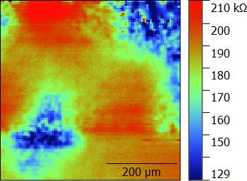
Using the Foil Cell both a commercial anode and cathode battery material were measured by ac-SECM. Measurements were performed using the M470+SP-300 system. In both cases area scan measurements were performed in 0.1 mol/L TetraButylAmmonium Iodide (TBA-I) in Propylene Carbonate (PC) using a 10 µm Pt UME probe. A common Pt sheet RE/CE was used. Measurements were performed at OCP with an ac modulation of 100 mV and a frequency of 250 kHz. At this frequency in 0.1 m/L TBA-I in PC ac-SECM measurements of conductive samples show a reduction in impedance as the tip-substrate distance decreases, allowing for a distinction between conductive and insulative areas. For both samples a 500 µm x 500 µm area with a step size of 5 µm, and a scan rate of 50 µm/s was used. Post processing was performed using the Gwyddion software.
The resulting area scans performed on the anode and cathode materials are shown in Fig. 5 and 6 respectively. In both cases the impedance was lower when measured over the sample surface than when the probe was in bulk, implying a conductive nature. It is likely that for both samples the changes in impedance seen throughout the area scan have arisen from differences in sample topography across the surface. This is particularly the case for the cathode material for which localized swelling was apparent on completion of the SECM measurements.

Figure 5: An ac-SECM measurement was performed on a commercial anode material in 0.1 mol/L TBA-I in PC.
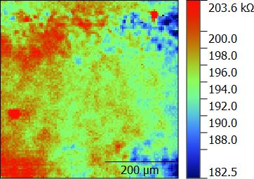

Figure 6: A commercial cathode material was measured by ac-SECM using a 10 µm Pt UME probe.
Conclusion
The use of the Foil Cell has been demonstrated for two distinct types of flat, foil type samples. Furthermore, it was shown that the Foil Cell can be used for both biased and unbiased samples. Finally, it was seen that using the Foil Cell instead of traditional cell configurations can reduce the setup time required by the user, whilst giving them confidence the results they measure have not been influenced by edge effects, or poorly insulated samples.
Acknowledgements
The two electrodes measured in this work were purchased by Karlsruhe Institute of Technology (KIT), Institute for Applied Materials – Energy Storage Systems (IAM-ESS). These were provided for measurement as samples of commercial-grade electrode materials.
References
- Gwyddion data analysis software gwyddion.net


