

Internal Resistance series. Part III: Which techniques should I use to investigate the internal resistance of a battery?
Latest updated: November 18, 2024Internal Battery resistance Part III:
Which techniques should be used to investigate the internal resistance of a battery?
Introduction
The field of battery and energy storage continues to grow exponentially with the development of consumer electronics and electric vehicles, among other key technologies. As a result, laboratories and industry are constantly looking to find new ways of improving battery performance and gaining competitive advantage, notably via reliability and longer battery life. They also need to understand and quantify battery degradation during its cycle life. One of the key parameters affecting those challenges is battery internal resistance. This series of 3 articles will help you to understand what internal resistance is and how it can be measured.
DCIR: Direct Current Internal Resistance
DCIR method is available in both EC-Lab® and BT-Lab® software. It can also be added to the ModuloBat technique as a sequence. DCIR was designed to determine the internal resistance of a battery, called $R_\mathrm{dc}$, using the continuous (DC) method and following Sections 7.6.1 and 7.6.2 of the IEC 61960 norm.
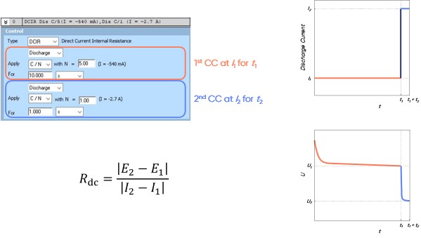
Figure 1: $R_\mathrm{dc}$ is defined in detail in the second article of this series.
This $R_\mathrm{dc}$ resistance is one of the key parameters used to evaluate battery quality and its variation upon cycling is significantly related to its performance. In an ideal scenario, this value should be as low as possible and should not change over time.
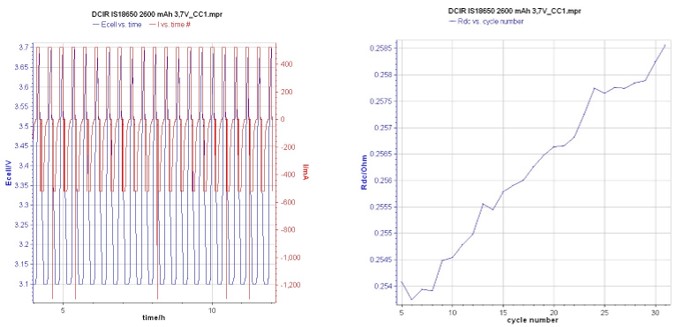
Figure 2: Current and voltage vs. time graph obtained using DCIR method. Obtained from a Li-ion battery cycling.
ACIR: Alternating Current Internal Resistance
Similarly, the ACIR method is available in BioLogic software. It can be used in galvano control mode (G-ACIR) or in potentio control mode (P-ACIR). Both are used to determine the internal resistance of a battery using the alternating (AC) method. G-ACIR allows experiments to be carried out using the following section 7.6.1 of the IEC 61960 norm which gives a measurement method of this resistance, called $R_\mathrm{ac}$.
The principle is to apply an AC current – or potential if P-ACIR is used – at a single frequency, typically 1 kHz, and to measure the response in voltage (or current).
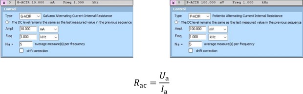
Figure 3: ACIR methods (left: Galvano mode; right: Potentio mode).
$R_\mathrm{ac}$ is defined in detail in the second article of this series.
How to use these data?
In both cases (DC and AC measurements), the calculation of the resistance is automatically performed by the software. The user has several ways to access these results:
- During the experiment, the global view and the experiment status bar show the last calculated $R_\mathrm{ac}$ or $R_\mathrm{dc}$

Figure 4: Global view window (top); Experiment status bar (bottom).
- After the experiment, the user has the possibility to study the changes in resistance over the cycle number on a spreadsheet – using the “Summary per protocol or cycle” analysis tool – or directly on the graph.

Figure 5: Summary per protocol or cycle window.


