

Better image resolution in SVET and LEIS using low conductivity electrolyte
Latest updated: May 27, 2025Local Electrochemical Impedance Spectroscopy (LEIS) and Scanning Vibrating Electrode Technique (SVET) are complementary techniques, often used together in local corrosion studies. SVET is used to determine the local current density of a sample in solution. LEIS, on the other hand, is used to measure the local impedance of a sample in solution. Both techniques rely on the potential gradient which develops above a sample in solution. In the case of SVET this is a dc potential gradient which develops over a naturally active, or biased sample, while in the case of LEIS this is an ac potential gradient which develops over a sample with an ac bias applied [1]. Although different mechanisms are used, both LEIS and SVET exploit the fact that at different heights above the sample different potentials will be measured. In SVET the probe is vibrated at a known amplitude, resulting in an ac potential signal due to the probe sampling at different positions during its vibration, Fig. 1a. LEIS instead uses a bi-electrode probe. In this case the two electrodes are separated by a known distance, allowing the ac potential to be measured at two positions with a known separation, Fig. 1b. Because of their dependence on the potential gradient in solution, both SVET and LEIS are dependent on the conductivity of the electrolyte used, and therefore researchers should consider their electrolyte conductivity carefully for the best results.
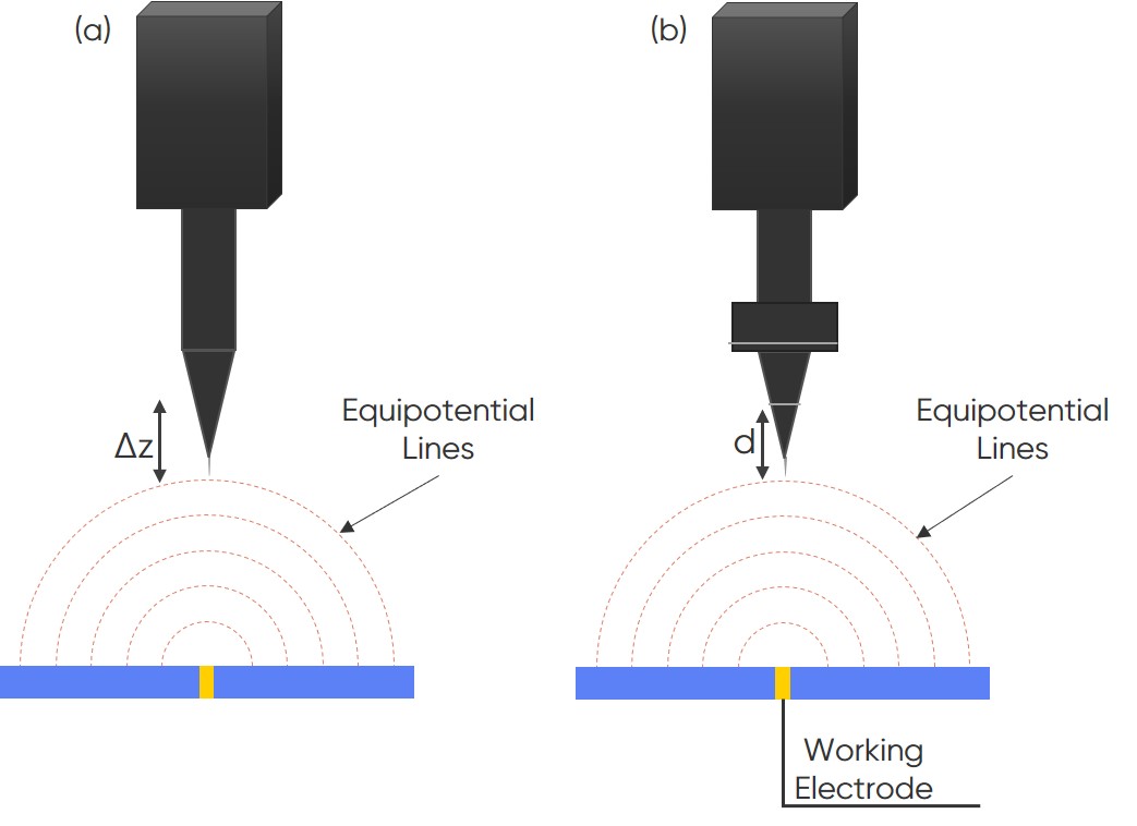
Figure 1 : The Scanning Vibrating Electrode Technique (SVET) is illustrated in (a). The probe is vibrated at a known distance (Δz) to measure at different equipotential lines. Local Electrochemical Impedance Spectroscopy (LEIS) is illustrated in (b). The electrodes of the bi-electrode probe are separated by a known distance to measure at different equipotential lines.
Why does electrolyte conductivity matter?
The potentials measured in SVET and LEIS (dc- and ac-potential respectively) are dependent on Ohm’s Law, with the potential in solution at the probe, $\phi$, given by:
$$\phi = \frac{I}{2 \pi \kappa R} \tag{1}$$
Where $I$ is the sample (point source) current, $\kappa$ is the solution conductivity, and $R$ is the distance from the sample (point source) [1, 2]. From this we can see that the potential measured is inversely proportional to the electrolyte conductivity. Stronger electrolyte conductivities therefore result in weaker potential gradients, making the SVET and LEIS signals weaker at a given distance than when a weak electrolyte is used. Simulations have also shown that low conductivity electrolytes allow for localization of features in measurements, which is not the case in high conductivity electrolytes [3].
The practical effect of electrolyte conductivity on SVET and LEIS
Keeping in mind that weaker electrolytes result in stronger potential gradients above the sample, and better localization of features in SVET and LEIS measurements, researchers may find they need to work with a weaker electrolyte in SVET and LEIS studies, than in bulk studies, to obtain good data. It is sometimes possible to work with a stronger electrolyte by moving the probe closer to the sample, but this is not always the case.
In SVET and LEIS there is also an assumption that electrolyte conductivity is uniform throughout the measurement, or series of measurements. Researchers should therefore take precautions against the evaporation of electrolyte throughout their studies. The resulting increase in electrolyte conductivity means measurement calibrations only hold true at the start of the study [4]. Precautions can be as simple as using a large volume cell, like the TriCell, for measurements.
A further note on LEIS
For LEIS it must also be considered that the electrolyte conductivity affects the usable frequency range. Using a low conductivity electrolyte will allow for improved resolution of the ac current. While working in a high conductivity electrolyte will reduce the effect of stray capacitance in the high frequency domain [5].
Measuring Conductivity
Although electrolyte conductivity can be measured using a conductivity meter, it is also possible to use any potentiostat with EIS capabilities to perform the same function. In this case researchers can measure the EIS of the system, regardless of its kinetics, fitting the results to find the ohmic resistance, and from this the conductivity. This is shown in more detail in Ohmic drop correction: a means of improving measurement accuracy.
Examples
To demonstrate the effect of the electrolyte conductivity on SVET an experiment was performed in two electrolytes of different conductivities. The two electrolytes selected were tap water, as a low conductivity electrolyte, with a measured conductivity of 145 µS/cm, and as a higher conductivity electrolyte a 5 x 10⁻³ mol L-1 NaCl solution, with a measured conductivity of 590 µS/cm. The results are shown in Fig. 2.
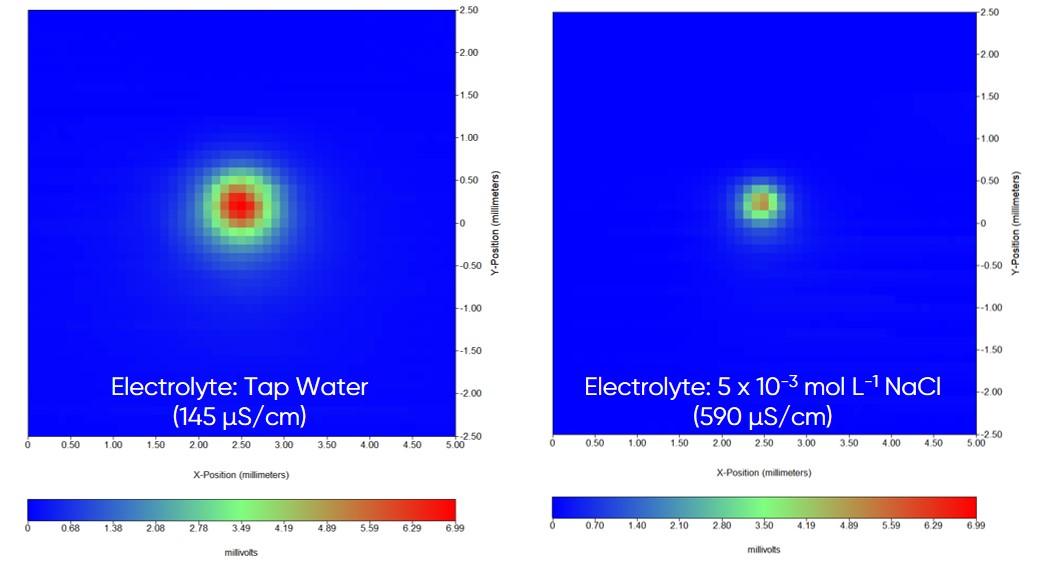
Figure 2 : A comparison of SVET measurement of a point in space sample in a low conductivity electrolyte, tap water (left), and a higher conductivity electrolyte, 5 x 10⁻³ mol L-1 NaCl (right), is shown. The raw potential SVET data is shown for easier comparison.
To demonstrate the effect of the electrolyte conductivity on LEIS an experiment was performed in two electrolytes of different conductivities. As a low conductivity electrolyte tap water, in this case with a measured conductivity of 134 µS/cm, and as a higher conductivity electrolyte, a 5 x 10⁻³ mol L-1 NaCl solution with a measured conductivity of 655 µS/cm was selected. The results are shown in Fig. 3.
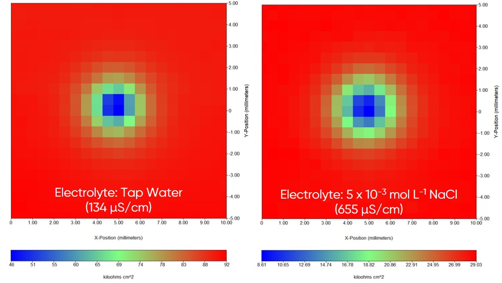
Figure 3 : A comparison of LEIS measurement of a point in space sample in tap water, with a conductivity of 134 µS/cm (left), and a 5 x 10⁻³ mol L-1 NaCl solution with a conductivity of 655 µS/cm (right), is shown.
Conclusion
As shown throughout this article the electrolyte conductivity has a crucial role in SVET and LEIS measurements. Researchers should carefully consider the electrolyte to achieve the best results. When possible, users should work with a low conductivity electrolyte. If this is impossible users may be able to work with stronger electrolytes by working with smaller probe to sample distances.
References
- Zou, D. Thierry, H. S. Isaacs, J. Electrochem. Soc. 144, 6 (1997) 1957-1965
- S. Isaacs, M. P. Ryan, L. J. Oblonsky, “Mapping currents at the corroding surface/solution interface”, Corrosion 97. 52nd annual corrosion conference of the National Association of Corrosion Engineers: economics and performance – bridging the gap and NACExpo (1997)
- Montoya, F. R. García-Galván, A. Jiménez-Morales, J. C. Galván, Electrochem. Comm. 15 (2012) 5-9
- C. Bouali, A. C. Bastos, S. V. Lamaka, M. Serdechnova, M. G. S. Ferreira, M. L. Zheludkevich, Electroanal. 31 (2019) 2290-2298
- Palumbo de Abreu, C. Molena de Assis, P. H. Suegama, I. Costa, M. Keddam, H. G. de Melo, V. Vivier, Electrochimica Acta 233 (2017) 256-261


