

What are PEM Fuel Cells and Electrolyzers?
Latest updated: November 18, 2024Introduction
Interest in fuel cell and electrolyzer technology is at an all-time high because combined, these two technologies have the potential to integrate into a complete green energy solution [1-2]. In this article we will explain the basic principles behind fuel cells / electrolyzers and show how potentiostats are used to qualify fuel cell and electrolyzer performance.
Although fuel cells and electrolyzers are two separate technologies, each with their own set of challenges, materials, and testing specification needs, it is helpful to discuss the two technologies in parallel. Fuel cells are electrochemical cells that convert chemical energy into electricity and electrolyzers convert electrical energy into molecules with high potential energy densities. The most common example is that of water splitting shown in Eq. (1).
$$2 \text H_2 \text O \rightleftarrows 2 \text H_2 + \text O_2 \tag{1}$$
Figure 1 represents a schematic of a PEM (proton exchange membrane) fuel cell, where the system is fed with a fuel (in this case $\text H_2$) and an oxidant (here $\text O_2$, contained in air) and electricity and water are the products (reverse direction of Eq. (1)). In an electrolyzer, schematic in Figure 2, the system is fed with water and electricity is used to split water into $\text H_2$ and $\text O_2$ (forward direction of Eq. (1)).

Figure 1. Schematic of a fuel cell
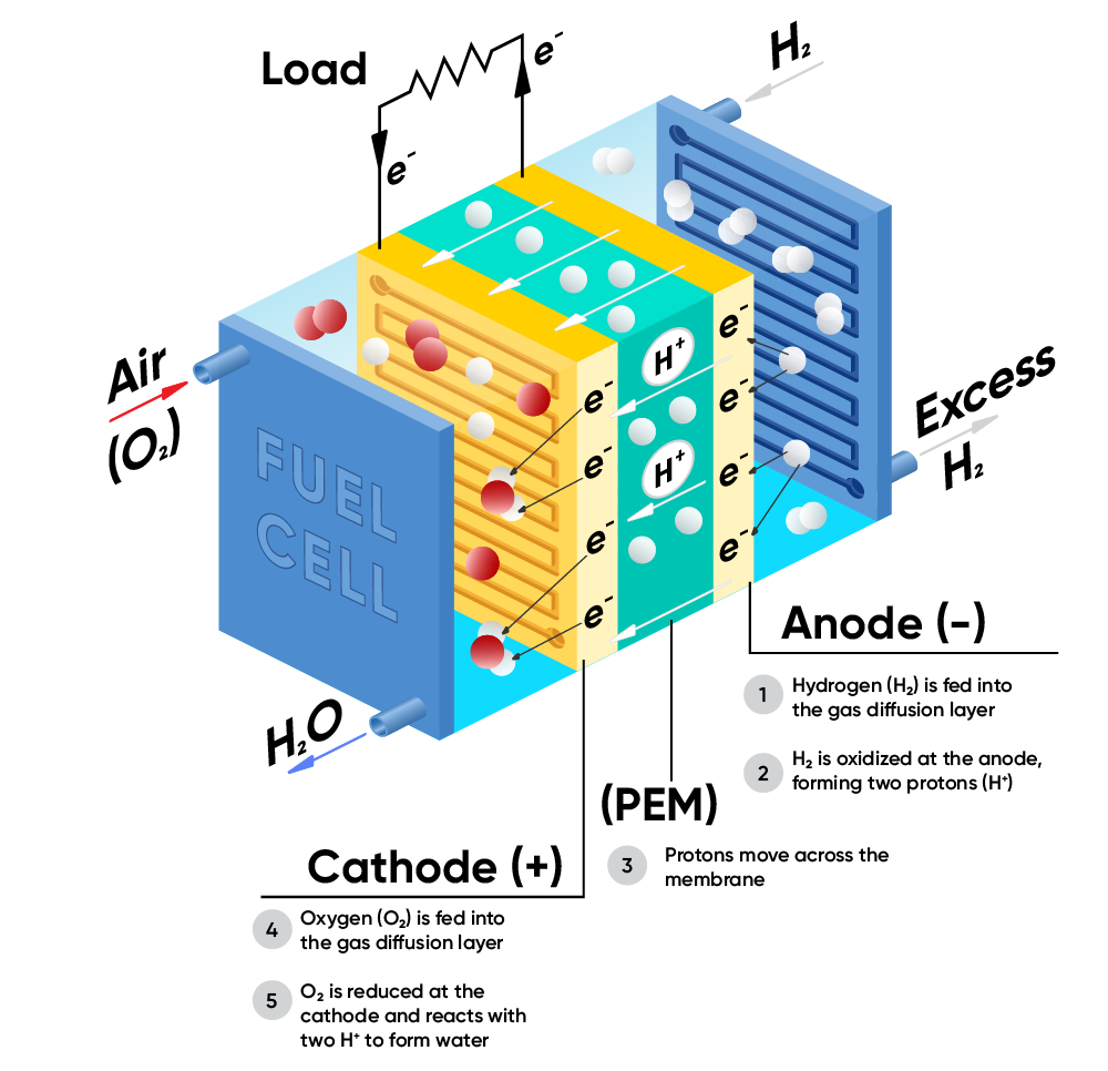
In the fuel cell, the reduction of $\text O_2$ occurs at the cathode
$$\text O_2 + 4\text H^+ + 4 \text e^- \rightarrow 2\text H_2 \text O \tag{2}$$
And the oxidation of $\text H_2$ occurs at the anode
$$2\text H_2 \rightarrow 4 \text H^+ + 4 \text e^- \tag{3}$$
The reverse reactions occur at the cathode and the anode of an electrolyzer.
The main focus for fuel cells is being directed towards applications for backup energy generation and for the transportation industry [3]. It is now recognized as a suitable substitute for petrol in heavy duty vehicles, for example, in 2020 the US department for energy launched the Million Mile Fuel Cell truck program [4] to develop the technology, and some truck manufacturer are now in the phase of tests on public roads with plans for commercialization between 2025 and 2030 [5]. In the future, as efficiency improves and costs decrease, they could also complement batteries across all vehicle types, solving the sourcing problem of rare elements used in batteries. However, this technology is still evolving, and cost-effective solutions must be found for hydrogen production, storage, distribution and safety for it to be a viable energy source [6].
The 2015 Paris agreement, which addresses the need to limit global warming, has boosted investment in $\text H_2$ technology. Plans have been made to considerably reduce greenhouse gas pollution, to create a carbon-free power sector, and to find alternatives to fossil fuels in order to reach a net-zero emission. But fuel cells alone cannot lower greenhouse gases because traditional hydrogen production, called ‘grey’ hydrogen, is very polluting and is made by reforming natural gas as product of methane decomposition:
$$\text {CH}_4 + 2\text H_2 \text O \rightleftarrows \text {CO}_2 + 4 \text H_2 \tag{4}$$
In this reaction, $\text {CO}_2$ is a byproduct and when released into the air, it contributes to greenhouse emissions. Carbon capture methods have been developed to store the $\text {CO}_2$ underground and to reuse it in industry but $\text H_2$ production using this route still requires methane.
Electrolyzers, on the other hand, can produce $\text H_2$ in a process known as electrolysis or water splitting. Water is fed into the system, an external current is applied, and hydrogen and oxygen are evolved. If the current applied is from a renewable energy source (e.g., solar, wind or hydroelectric power), then this reaction is carbon neutral, and the product is termed ‘green’ hydrogen.
Figure 2. Schematic of an electrolyzer

One of the main limitations to the development of hydrogen-based technology is its production cost. In 2019 the cost to produce $\text H_2$ by electrolysis was around 8 USD/kg, which was about 5-8 times the cost using methane but efforts to reduce production cost are on-going and new advancements are being made every day. The US government has committed significant funding to electrolysis research, with the aim of achieving cost targets of 1 USD/kg by the year 2030 [7].
How are potentiostats used in PEM fuel cell and electrolysis research?
Potentiostats are used to qualify and test fuel cells and electrolyzers because they can control voltage and current and are used to build polarization curves or run cyclic voltammetry or other electrochemistry techniques. However, it’s important to note that these devices operate in two distinct modes: direct current (DC) and alternating current (AC).
Potentiostats can be a source of current (electrolyzer mode) or a current sink (fuel cell mode). The ability for a potentiostat to operate in negative current conditions (as a sink) or in positive current conditions (as a current generator) can be found in the specifications, where the maximum amplitude of the current needed is defined by the size of the PEM to be studied.
Table 1. Maximum amplitude needed for PEM fuel cells / electrolyzers depending on size.
| Typical current per cm2 (A) | Current needed for 25 cm2 cell (A) | |
|---|---|---|
| PEM fuel cell | – 1 to -2 | – 25 to -50 |
| PEM electrolyzer | 3 | 75 |
The optimal operating conditions of a fuel cell or electrolyzer are determined using a polarization curve (Figure 3 and Figure 4). The initial point of a polarization curve, where the current density is zero, is called the Open Circuit Voltage (OCV). The OCV measures the voltage reduction resulting from hydrogen crossover across the membrane. This measurement is taken in the absence of any applied current within the system and the voltage output is accurately determined. The OCV for fuel cells is always below the theoretical voltage of 1.2 V required for water splitting, whereas it will be above 1.2 V for electrolyzers.

Figure 3. Representative polarization curve of a fuel cell. The over-all cell performance is a combination of potential losses.

Figure 4. Representative polarization curve for an electrolyzer. The overall performance is a combination of potential losses.

For both Fuel Cells and Electrolyzers the aim is to have minimum total losses so the polarization curve is the ‘flattest’ (at a given current density the cell voltage should be maximum for a fuel cell and minimum for an electrolyzer).
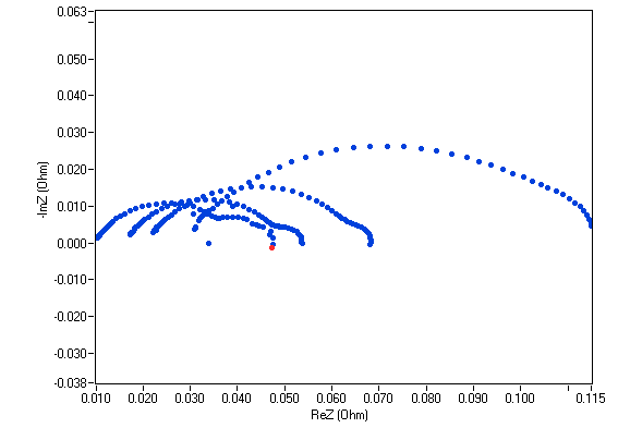
Potentiostats can also be used for impedance measurements (EIS). In this mode the potentiostat generates a small sinusoidal AC signal (usually 5 to 10% of the amplitude of the DC signal) over the DC signal. The EIS is a multi-frequency technique which provides in-situ information on different contributors of the fuel cell or electrolyzer to the impedance. Depending on the frequency used, some contributors will respond, more or less, to the AC perturbation, and the user would be able, for example, to get information on the ohmic resistance or characterize the mass transfer resistance on the electrodes. Figure 5 shows an example of a Nyquist plot for a 25 cm2 fuel cell over a 7-loop staircase GEIS experiment (i.e., EIS measurements with varying load currents).

Figure 5. Nyquist plots resulting from a staircase GEIS measurements on a 25 cm2 fuel cell.
The right pick for your fuel cell or electrolysis research

Figure 6. Range of BioLogic instruments used through various stages of fuel cell and electrolyzer research and testing.
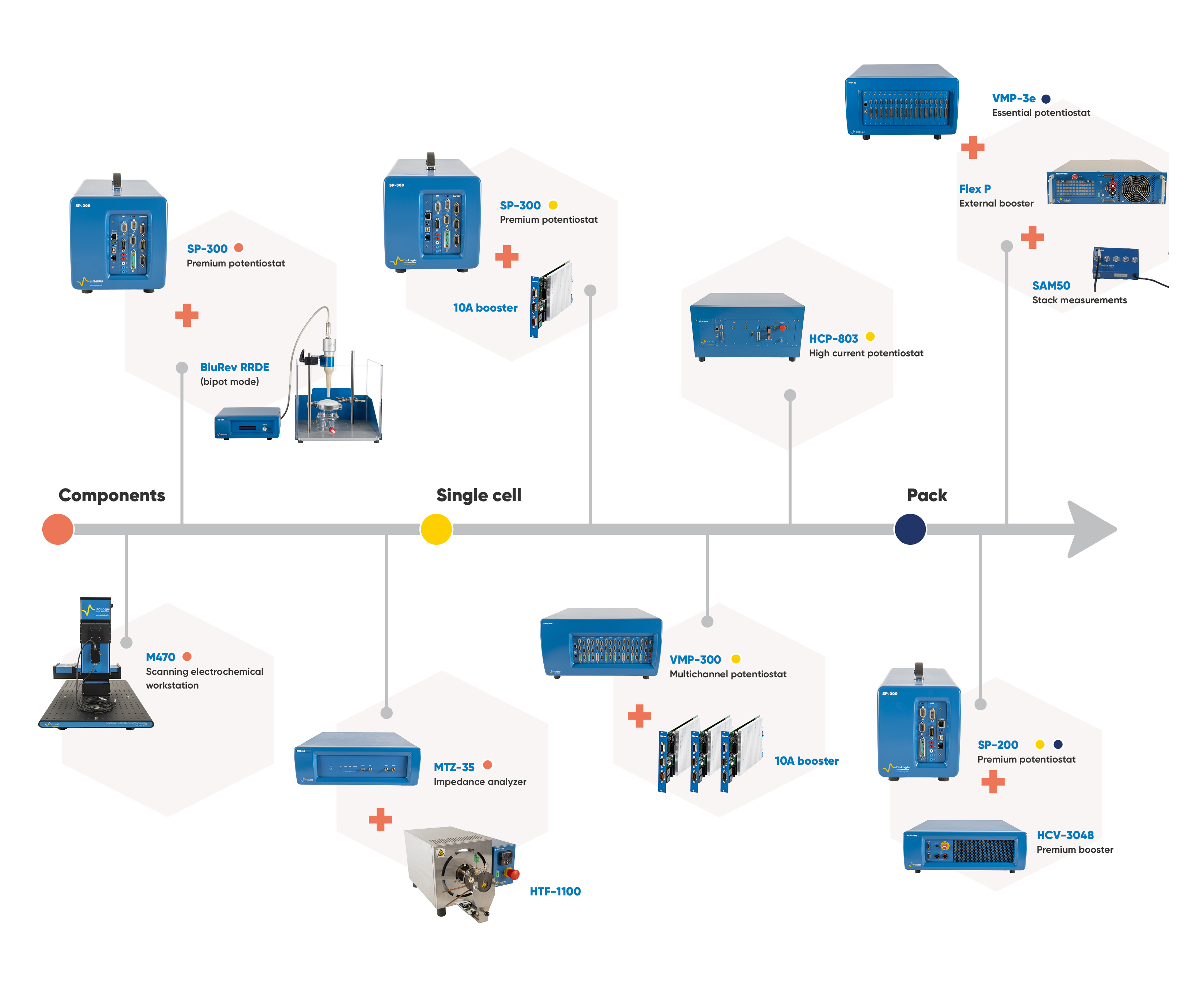
BioLogic offers a large range of instruments that are well suited for fuel cell and electrolyzer studies (see Figure 6). The best choice will mainly depend on:
- The size of your cell: the surface of the membrane determines the maximum current required. If you work with small stacks the number of cells in the stack will also define the maximum voltage needed. For example, in a fuel cell, a single cell will generate around 1 V so if you work with a stack of 10 cells you must select a potentiostat able to measure 10 V.
- The level of modularity required: do you only want a potentiostat for a single purpose? Or do you wish to use the potentiostat for other applications in your lab? If so, you’ll want the ability connect boosters or add more channels autonomously. You may also consider modularity as a solution to scale-up without needing to buy a completely new system each time. For example, you work with 25 cm2 cells now, but you plan build up to 100 cm2 cells or you want to start out on a single cell but need the option to test short stacks later. BioLogic potentiostats come in a range of modular systems, including external and internal boosters.
- The level of integration required: If you need to integrate the potentiostat into a commercial or homemade bench station so you can control the potentiostat from your own software, EC-Lab® offers a developer package for OEM integration. You can then use one software for data acquisition and to communicate with your gas station, e.g., synchronize Start/Stop commands or change operating conditions (temperature, pressure, humidity, flow rate…).
Premium Potentiostat with 10 A booster boards
Biologic Premium Potentiostats have the ability to run parallel 10 A boosters to reach the current values required for fuel cell and electrolyzer applications. You can reach up to ±40 A in a VSP-300 and up to ±150 A in a VMP-300, with negative voltage capability. Using premium potentiostat and 10 A boards, 2 MHz EIS is possible, which gives outstanding precision for the investigation of internal processes of the cell. Users also get access to unique EIS quality indicators with EC-Lab®.
The VMP-300 is the system of choice if you have scale-up needs or need a flexible system for a multi-user facility.Figure 7 shows how you can adapt the number of boosters boards to the size of the cells you want study. For example, if you work with 10 cm2 cells then 3 boosters boards are enough to reach 30 A. When you go to bigger cells, like 25 cm2, then you can use 7 boards and reach 70 A. With a maximum current of 150 A, the VMP-300 can even study 50 cm2 cells or several stacked 10 cm2 cells. Accessories are available to group booster cables and make cable management simpler.

Figure 7. Example of a VMP-300 chassis filled with 10 A boosters configured to easily scale-up from 30 A to 120 A to work with stacked cells

The premium potentiostats can be fully customized and integrated into complete bench stations. All models are compatible with the EC-Lab® development package.
HCP-803
This is potentiostat with an integrated booster that can reach ± 80 A and ± 3 V. It combines the quality and precision of a research potentiostat. It perfectly matches single-cell fuel cell and electrolysis applications thanks to its voltage range. It can be operated as a load or current generator and would be ideal for all cells smaller than 25 cm2. When operated with high current, EIS can go up to 10 kHz. The booster part of the instrument can also be disconnected to allow research class specifications up to 1 MHz. The HCP-803 also offers broad integration capabilities using the EC-Lab® development package.
Essential Potentiostats with high current FlexP boosters
The FlexP are boosters designed for the Essential Potentiostat range. They exist in 2 formats: The FlexP0012, which is more adapted for electrolyzers thanks to high current limit and negative voltage availability, and the FlexP0060, which is more adapted to fuel cell stacks, as you can reach 60 V.
Table 2:
Table 2. Maximum current and voltage achieved using BioLogic Essential Potentiostats and FlexP Boosters.
| FlexP0012 | FlexP0060 | |
|---|---|---|
| Current range | ± 200 A | ± 50 A |
| Max current in || | ± 800 A (4 units) | ± 200 A |
| Voltage | -2 to 12 V | 0 to 60 V |
The FlexP0012 booster can run in parallel, so you can go up to ± 800 A, which makes it perfectly suited for large single-cell fuel cells, electrolyzers and short stacks. It can reach 10 kHz EIS. It can be used as load or current generator from one slot of the Essential potentiostat when other potentiostats channel will measure voltage on each cell of the stack. Using stack mode, you can get the total impedance of the cell and the individual impedance of each element. Integration capabilities are lower with the FlexP0012 but it can still synchronize easily with test stations using a Trigger In and Out signal and the user will fully benefit from EC-Lab® software to design their experiments and collect data.
Conclusions
Fuel cells and electrolyzers are two emerging technologies for energy storage and conversion. However, there are some challenges to their widespread adoption, the biggest being the cost of producing green hydrogen. Potentiostats are essential tools for developing and studying fuel cells and electrolyzers. BioLogic offers several solutions to the challenges of studying fuel cells and electrolyzers, such as modular potentiostats and boosters.
References
- Fan, L.; Tu, Z.; Chan, S. H. Recent Development of Hydrogen and Fuel Cell Technologies: A Review. Energy Reports 2021, 7, 8421–8446. https://doi.org/10.1016/j.egyr.2021.08.003.
- Shiva Kumar, S.; Himabindu, V. Hydrogen Production by PEM Water Electrolysis – A Review. Materials Science for Energy Technologies 2019, 2 (3), 442–454. https://doi.org/10.1016/j.mset.2019.03.002.
- Cullen, D. A.; Neyerlin, K. C.; Ahluwalia, R. K.; Mukundan, R.; More, K. L.; Borup, R. L.; Weber, A. Z.; Myers, D. J.; Kusoglu, A. New Roads and Challenges for Fuel Cells in Heavy-Duty Transportation. Nat Energy 2021, 6 (5), 462–474. https://doi.org/10.1038/s41560-021-00775-z.
- Home | M2FCT. https://millionmilefuelcelltruck.org/ (accessed 2023-11-13).
- Pollet, B. G.; Kocha, S. S.; Staffell, I. Current Status of Automotive Fuel Cells for Sustainable Transport. Current Opinion in Electrochemistry 2019, 16, 90–95. https://doi.org/10.1016/j.coelec.2019.04.021.
- Wang, Y.; Ruiz Diaz, D. F.; Chen, K. S.; Wang, Z.; Adroher, X. C. Materials, Technological Status, and Fundamentals of PEM Fuel Cells – A Review. Materials Today 2020, 32, 178–203. https://doi.org/10.1016/j.mattod.2019.06.005.
- Hydrogen Shot. Energy.gov. https://www.energy.gov/eere/fuelcells/hydrogen-shot (accessed 2023-10-23).


