

Sweep scan in Scanning Kelvin Probe (SKP) experiments Scanning Probes – Application Note 24
Latest updated: June 17, 2024Scanning Kelvin Probe (SKP) measures the contact potential difference between a probe and sample, a value is directly related to the work function, and corrosion potential of a sample. Although of great use the applicability of SKP, like other scanning probe microscopies, can be limited by the time to perform a measurement. In this note a laser marked anodized aluminium sample is measured to demonstrate how sweep scan can be used to perform fast, high quality, measurements.
Video demonstration
Scanning Kelvin Probe can be used to determine variations in corrosion potential across a sample. In this video we demonstrate the use of the sweep scan mode on the SKP470 to perform fast, high quality SKP measurements of a laser marked anodized aluminium sample provided by Renthal Ltd (https://www.renthal.com/). Further information can be found in the related app note: AN #24: The use of sweep scan in Scanning Kelvin Probe (SKP) experiments.
Introduction
Scanning Kelvin Probe (SKP) measures the contact potential difference, or Volta potential, between the SKP probe and the sample under study. It is possible to correlate the Volta potential measured with the work function or the corrosion potential of the sample understudy.
A limiting factor in SKP, and other scanning probe experiments, can be the length of the experiment. This is particularly the case when large scan areas, of a few centimeters or more, are of interest. In these cases, using step scan, in which the probe stops to measure at each point for, can lead to prohibitively long experiments. If the Volta potential is measured continuously, as in sweep scan mode, the SKP experiment can be noticeably reduced, making it highly applicable to the measurement of large areas.
This note uses the M470 to perform SKP measurements of a laser marked anodized aluminum sample, provided by Renthal Ltd. Laser marking is an industrially important technique used to inscribe information and decoration on parts. When used on anodized aluminum the laser marker removes the anodized layer exposing the underlying aluminum [1]. The laser marking was done at different intensities and frequencies to form a grid of varying exposures. Measurements were performed in step and sweep scan to demonstrate the applicability of sweep scan to large area SKP experiments.
Sweep vs. step scan
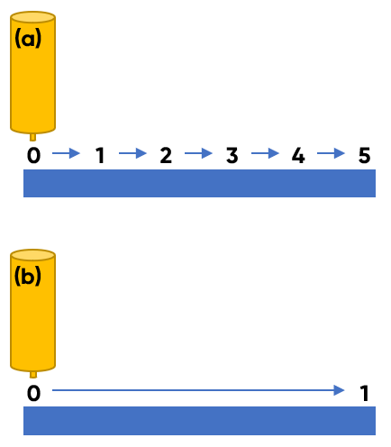
Scans for all dc techniques on the M470 can be performed in either step scan or sweep scan mode. In step scan mode the probe measures the first point in each line before moving to the next point, pausing, and performing the next measurement. This move-pause-measure cycle is repeated at each point until the line is complete, this is illustrated in Fig. 1a. Because the probe pauses at each point multiple samples are measured and averaged. Step scan is used, therefore, for measurements with the lowest noise. In sweep scan, Fig. 1b, the probe does not stop and measures continuously throughout each line. Because the velocity of the probe is accurately known measurements are taken at set time intervals and converted into the position data of interest. As will be shown in this note sweep scan is beneficial when the shortest experiments are needed, for example when the size of the scan area could lead to prohibitively long experiment durations.

Figure 1: Step scan (a) and sweep scan (b) modes are illustrated.
Experimental
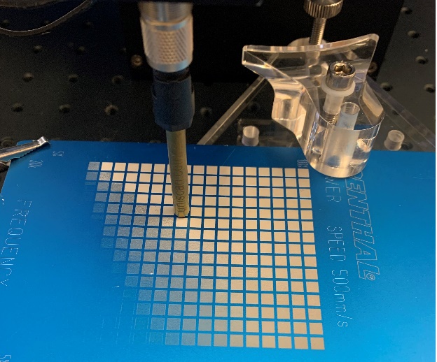
Laser marking of the blue anodized aluminum sample was performed at a speed of 500 mm/s. In the x direction the frequency increased from 30 kHz to 100 kHz, while in y the power increased from 5% to 100%. The result is a grid of 15 squares in x, and 17 squares in y, Fig. 2.
The laser marked sample was mounted on the TriCellTM and levelled on the M470 baseplate. A crocodile clip was used to make electrical connection to the sample. A 500 µm tungsten probe (U-SKP370/1) positioned within 100 µm of the sample surface, was used for all measurements.

Figure 2: The laser marked anodized aluminum sample.
Measurements comparing sweep scan and step scan were performed over a 1 cm x 1 cm area, covering nine different laser marked squares. Both measurements used a 100 µm step size in x and y, and a velocity 500 µm/s.
To illustrate the effect of sweep rate on the measurement quality a second sweep scan experiment was performed over a 1 cm x 1 cm area. Only the sweep velocity was changed to 1000 µm/s.
To rule out the effect of topography on the final SKP measurements a 1 cm x 1 cm step scan measurement was performed using height tracking. In this test the sample topography was first measured with Capacitive Height Measurement (CHM), and then input into the SKP measurement to maintain the probe to sample distance. The step size was 100 µm in x and y, and the velocity was 500 µm/s.
Finally, a sweep scan measurement over an area of 7.5 cm x 8.4 cm, to cover the entire laser marked grid, was performed. The step size and velocity were 250 µm, and 500 µm/s respectively.
Final area maps were produced using Gwyddion [2] to rotate them to match the orientation of the laser marked piece.
Results
Sweep scan vs step scan
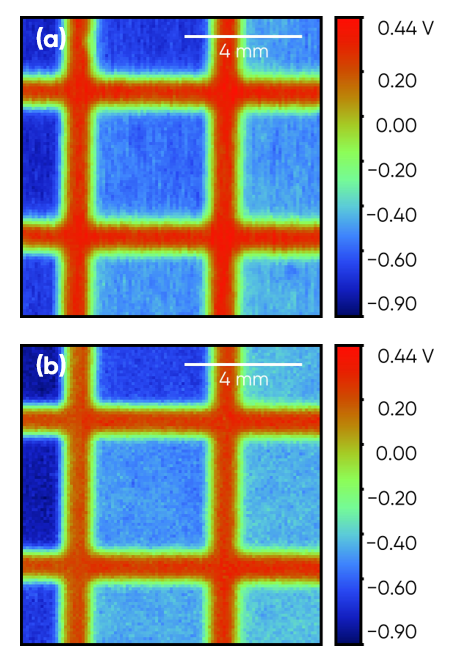
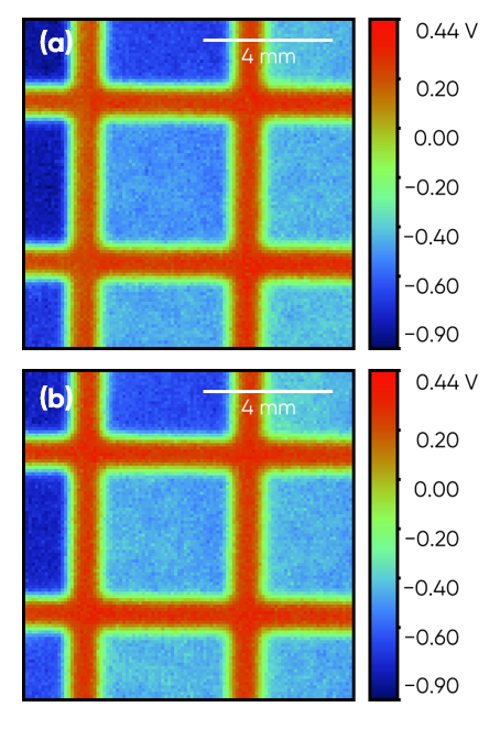
Fig. 3 shows the initial sweep and step scan experiments. These have been rotated 90° counter clockwise from the measurement direction to match the orientation of the laser marked sample. There is little difference between the Volta potentials measured in either mode. In the axis of the sweep scan, however, the boundary between the anodized layer and the laser marked squares are sharper in the step scan than in the sweep scan measurement. This is a result of the data averaging which occurs in the step scan measurement, improving the final signal. The signal improvement, comes at a cost. In this example the 1 cm x 1 cm area scan took 42.5 minutes in sweep scan mode, and 4 hours and 56 minutes in step scan mode, an almost seven-fold increase in experiment duration.

Figure 3: SKP measurement of the same area of laser marked sample using the (a) sweep scan, and (b) step scan modes.
Effect of sweep rate
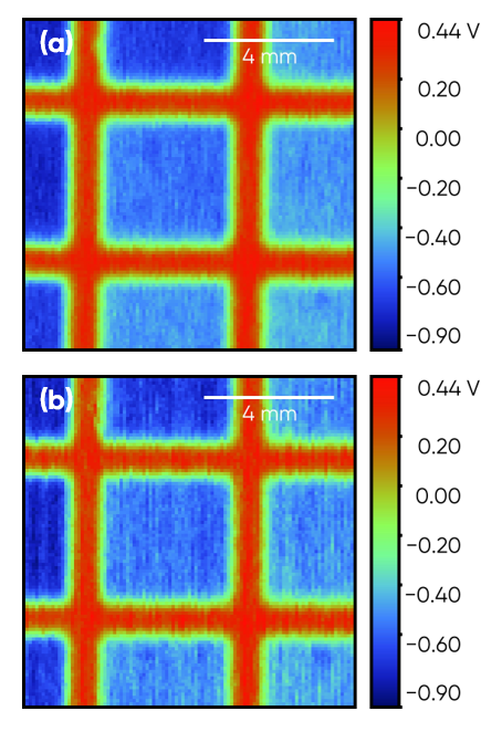
When using sweep scan it is important to note that while faster sweep rates reduce the experiment duration, they can also exaggerate the effect of noise, and degradation of the measurement signal can occur, as demonstrated in Fig. 4. Fig. 4a is the sweep scan performed at 500 µm/s, while Fig. 4b is performed at 1000 µm/s. While using the faster sweep velocity has reduced the measurement duration to 22.25 minutes, almost half as long as the sweep scan at 500 µm/s, the border between the laser marked square and anodized aluminum is further blurred. Furthermore, more variation in the signal measured within each laser marked square is seen. When using sweep scan, therefore, users must consider how the selected sweep rate will affect the final signal. By using a more conservative sweep rate users can still take advantage of the reduced experiment duration compared to step scan, while achieving sharper, higher quality measurements.

Figure 4: SKP sweep scan of the same area of a laser marked sample at (a) 500, and (b) 1000 µm/s
Topography effect
Before measuring the full laser marked grid it was necessary to rule out the possibility that the changes in Volta potential measured are related to changes in topography as a result of the laser marking of each square. To do this the same 1 cm x 1 cm area was remeasured in step scan mode with height tracking enabled, to maintain the probe to sample distance. The result of this measurement is compared to the original constant height SKP measurement in Fig. 5. When these two maps are compared no apparent difference in quality or magnitude of the measurement can be seen, therefore a topography effect can be ruled out.

Figure 5: SKP step scan measurement of the same area of a laser marked sample in (a)constant height and (b)height tracking mode.
Large area sweep scan
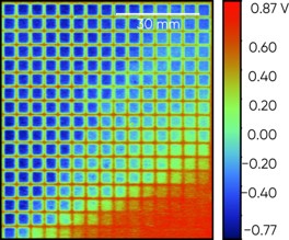
As a demonstration of the applicability of the use of sweep scan the final measurement was of the entire laser marked grid. Using a 500 µm/s sweep rate, for the highest quality measurement with the shortest experiment duration, the entire 7.5 cm x 8.4 cm grid was measured in just over 15.5 hours. Extrapolating from the original step scan measurement to measure an area of this size, with the same number of points, over two days would be needed, a length which could exclude the use of SKP to measure the sample.
The final sweep scan is shown in Fig. 6. This has been rotated 180° to match the orientation of the sample. In an SKP measurement the measured Volta potential can be directly related to the corrosion potential of a sample [3-5], with lower Volta potentials indicating a lower corrosion potential. Bearing this in mind, therefore, it can be seen that the laser marked regions have a lower corrosion potential than the intact anodized layer, as would be predicted. The corrosion potential also increases as the intensity of the laser marking decreases. Finally, it can be seen that potential changes can be detected in laser marked regions even where a visual change in the anodized layer has not occurred.

Figure 6: SKP measurement of the full 7.5 cm x 8.4 cm laser marked grid sample.
Conclusion
This note demonstrates the applicability of sweep scan mode, particularly for SKP measurements. While measurements with sweep scan can have a lower signal quality than those performed using step scan mode, this can be an acceptable compromise to noticeably reduce the experiment duration. This is particularly the case when large scan areas are of interest.
Acknowledgements
We warmly thank Renthal Ltd. for providing the samples used in this work.
Appendix: Sweep scan settings
When configuring SKP sweep scan experiments the Signal Conditioning and Backing Potential settings need to be updated from those used in step scan mode to ensure data sampling keeps up with the scanning speed. If sampling is too slow the signal will lag behind the real feature position, and appear unnaturally smooth. If too fast the data can oscillate resulting in excessively noisy data. While the exact settings, particularly the PID values, may vary between laboratories and samples, the Signal Conditioning and Backing Potential settings used for the 500 µm/s sweep scan are given below as a reference for users.
| Signal Conditioning | |
|---|---|
| Gain | 100 |
| Full Scale Sensitivity | 5 mV |
| Output Time Constant | 0.1 |
| Vibration Amplitude | 30 µm |
| Vibration Frequency | 80 Hz |
| Reference Phase | Manually set |
| Backing Potential | |
| P-Proportional | 0.700 |
| I-Integral | 0.005 |
| D-Derivative | 0.000 |
| PID Loop Rate (Hz) | 25 |
| ADC Sample Rate (Hz) | 1000 |
| Samples Averaged per Loop | 20 |
| Max PID Step per Loop | 0.5 |
| Max Control Output | 5.0 |
| Min Control Output | -5.0 |
References
- Lazov, H. Deneva, P. Narica, Environment. Technology. Resources. Proceedings of the 10th International Scientific and Practical Conference. Volume I, 2015, 108-115
- Gwyddion data analysis software http://gwyddion.net/
- Stratmann, H. Streckel, Corrosion Science, 30 (1990) 681 – 696
- Stratmann, H. Streckel, Corrosion Science, 30 (1990) 697 – 714
- Stratmann, H. Streckel, K. T. Kim and S. Crockett, Corrosion Science, 30 (1990) 715 – 734
Revised in 05/2021


