

Height tracking with the SKP370 or SKP470 module Scanning Probes – Application Note 1
Latest updated: June 13, 2024Abstract Local electrochemistry probe measurements and especially Scanning Kelvin Probe (SKP) are most commonly used in constant height mode.
This has two drawbacks:
1. The topography of the sample can affect the measurement, hence it is necessary to perform scans at constant distance.
2. Some samples can be non-flat or curved and cannot be measured in constant height mode because the tip would simply crash.
By using SKP as a capacitance measurement, it is possible to measure the topography of the sample surface. Topography data can then be integrated in the actual SKP scan to maintain the probe at a constant distance from the sample, also called height-tracking. The use of SKP is now extended to any non-flat samples.
The note shows how to operate M370/M470 Scanning Kelvin Probe in height tracking-mode.
Introduction
The signal strength of the SKP technique and thus the ability to extract sensitive data depends on numerous factors. The main influences are the work-function difference of the materials involved (sample and probe), the probe tip size, the vibration amplitude and the proximity of the vibrating probe to the sample surface.
A user may expect that the ambient noise throughout the M370 or M470 systems and the surrounding environment to remain approximately the same throughout an experiment, however, the signal strength can change due to variations in the parameters mentioned above.
Any measurement relies on a good signal to noise ratio, even that based on statistical techniques. At some point the noise can exceed the signal to such an extent that the measurement becomes indeterminable. To avoid this situation, the SKP370 or SKP470 user will want to maximize the signal strength in all cases, and will need to consider the effects of the parameters mentioned above to obtain good measurements.
One way to can enhance the signal to noise ratio is to ensure a small probe to sample distance and maintain this distance constant over the whole scan area. To do this successfully, it is necessary to have the sample’s topography information over the scan area and to relieve the probe’s position as dictated by this topography as the probe scans over the surface. There are a number of different techniques that can provide the sample’s topography information:
- Non-Contact Optical Surface Profiling (OSP)
- Scanning Electro-Chemical Microscopy (SECM)
- Intermittent contact Scanning ElectroChemical Microscopy (ic-SECM)
- Capacitive Height Measurement technique (CHM, SKP)
- Capacitive Tracking Measurement technique (CTM, SKP)
The CHM and CTM experiments are available to the user with the M370 or M470 SKP module and are demonstrated in this technical note.
Principles of CHM and CTM topology measurement.
Both of these techniques reply upon the principles of measuring the capacitance generated between the probe tip and the sample. When a voltage is applied between the probe and the sample, a quantity of charge is stored that is dependent on the capacitance generated by the sample and the probe,following this relationship :
$$Q = CV$$(1)
where Q is the charge, C is the capacitance and V is the voltage applied.
The capacitance C is dependent on the physical parameters of the system as follows:
$$C = \epsilon_r\epsilon_0\frac{A}{d}$$(2)
where A is the area of the parallel plates (effectively, the tip area), d is the distance that separates the plates of the capacitor (effectively, the tip to sample distance) and εr and ε0 are the relative permittivity and the permittivity of free space, respectively.
If the probe is vibrated in a sinusoidal manner, the distance (d) of the probe to the surface will also vary sinusoidally in time, and the capacitance on the system will vary accordingly.
$$C(t) = \epsilon_r\epsilon_0\frac{A}{d(t)}$$(3)
where t is the time
Consequently, the charge stored due to the change in capacitance will also change as follows:
$$Q(t) = C(t)V$$(4)
For the charge in the system to change, there must be an associated current flow; it is this current that is measured to provide an indication of the probe to sample distance d. A calibration constant k is calculated and applied to the measured current so that the distance of the probe to the surface is provided:
$$I(t) = kd(t)$$(5)
In the CHM (Capacitive height Measurement) mode, at each point in a sweep scan or a step scan experiment, the probe is rastered across the surface at a fixed height (fixed z-axis position) and the calibration is used to extract a probe to sample distance.
In the CTM technique, the distance (d) at the beginning of the experiment is set as the desired probe to sample distance. When the probe steps to the next position, if the measured probe to sample distance is different to the desired probe to sample distance, the probe will be repositioned until the desired setpoint is met. The amount of movement required to reposition the probe is measured (using the 100 nm optical encoders) and saved as the topology. Essentially, the probe maintains the initial probe to sample distance during the whole scan.
The relative advantages and disadvantages of both methods are listed in the following table. Table 1 : Advantages and disadvantages of the CHM and CTM techniques 
Topology relief using CHM.
Figures 1 and 2 are CHM and SKP area scan, respectively, obtained over a wear-mark of zinc coated steel sample after 24 h corrosion. Both the wear-mark and the corrosion have deformed the sample and any scanning Kelvin probe measurement would require topographical relief to extract surface details.  Figure 1: CHM topology area scan over a wear-mark of zinc coated steel sample after 24 h corrosion. The CHM experiment in Fig. 1 shows the distance from the probe to the sample, indicating a rounded wear mark of ~100 μm deep on the left-hand side of the sample. The peak at 138 μm is the wear-mark and the point at which the probe is furthest from the sample. The SKP experiment in Fig. 2 below uses height-tracking to relieve the surface topology of Fig. 1 before extracting SKP data. A probe to sample distance of ~40 μm is maintained throughout the whole area scan. The user is then able to extract surface related work-function measurements without interference from topology.
  Figure 2: SKP area scan obtained over a wear-mark of zinc coated steel sample after 24 h corrosion with topology relief from Fig. 1.
If the surface topology varies beyond the practical measurement capabilities of the CHM technique, the CTM is an alternative that can provide the same accuracy over a much wider range, albeit at a slower rate.
Topology relief using CTM.
Figure 3 shows a slightly corroded metal former with topology that is far beyond the abilities of CHM technique to measure. The system is set to use the CTM technique to register the precise topology every 100 μm over 36 mm2. Fig. 4 shows the resulting CTM scan, where the topography varies by around 700 μm from the edge to the centre making standard SKP measurements impossible.  Figure 3: Kelvin probe in close proximity (~220 μm) to curved metal former. (Actual CTM and SKP experiment data taken with the probe at ~40 μm from the surface).
  Figure 4 :CTM experiment results for a slightly corroded metal-former.
Figure 5 shows an attempt at performing a standard SKP scan without topology relief over the same area as scanned in Fig. 4. It is obvious that the sample’s formation affects the measurement: as the probe is far from the surface, the charge stored at the probe-air-sample interface is negligible and the resulting amplification is simply amplifying ambient noise. In reality, the probe is actually in reasonably close proximity to the surface over the central area of the scan and the data here should be representative of the sample’s surface features. However, the results from the areas where the probe is far from the surface are swamping any possibility of obtaining good data. 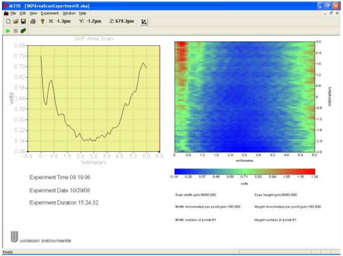 Figure 5 : SKP area scan over the curved metal former without surface topology relief.
In comparison, Figure 6 shows a Scanning Kelvin Probe area scan of exactly the same area of the sample shown in Fig. 5, the only difference being that the SKP probe was brought into close proximity to the sample (average of ~40 μm) and the CTM data shown here was used to maintain the probe at this distance over the full 36 mm2. It can be seen that the effect of the curvature on the SKP measurement was succesfully eliminated.  Figure 6 : SKP experiment performed over exactly the same area with height-tracking enabled, using the CTM data.
Conclusion
Using the height tracking facility in the M370 software allows a more accurate determination of the surface work function. The system is able to maximize the signal to noise ratio throughout the scan area by removing the effect of topology. The ability to perform height tracking is totally dependent on having the ability to measure and then use this height data. As demonstrated, it is possible to use the CHM and the CTM technique to obtain this data. CHM is faster but can only be used in cases where the topological changes are within a 100 μm range. For larger topographical changes, the slower CTM technique needs to be used.
References
The M370 and M470 are devloped, designed and manufactured by Uniscan Instruments, a Bio-Logic SAS company.This note was written by D. Lonsdale, Uniscan Instruments Ltd.


