

EIS pseudocapacitance Battery & Corrosion – Application Note 20
Latest updated: May 2, 2023Abstract
In equivalent circuit modeling, it is sometimes useful to substitute a RQ circuit with a RC circuit. In this application note, the impedance spectra of a Li-ion battery is modeled using an overall equivalent circuit that consists of a R/Q circuit from which the pseudo-capacitance can be calculated automatically by simply selecting the “PseudoC” option after fitting the data to the model. This note also demonstrates how to build and add a new circuit to the ZFit tool.
Introduction
With some systems, the plot of the Nyquist diagram shows a semi-circle whose center is below the real axis. This characteristic happens when the surface of the electrode in not totally smooth. This “depressed” semi-circle can be simulated with an R/Q circuit instead of an R/C circuit for the perfect semi-circle. It can then be useful to calculate an equivalent capacitance called a pseudo capacitance when using a Q element instead of a C element (Figure 1).
This calculation is only available for a circuit (R/Q). It corresponds to the determination of a capacitance value C at an angular frequency ωc = 2πfc corresponding to the maximum imaginary part on the Nyquist circle obtained by fitting with the circuit (R/Q). Then, this value is the solution of the following equation
$$\frac{1}{2\pi (RQ)^{\frac{1}{\alpha}}} = \frac{1}{2\pi (RC)} \Rightarrow C – Q^{1/ \alpha}R^{(1/ \alpha)-1}$$
with α and Q as the CPE parameters [1,2].

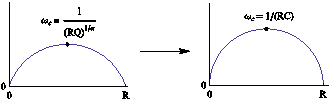
Figure 1: Equivalent electrical circuit RQ and RC with the corresponding impedance diagram.
Experimental Part
A lithium-ion battery, with LiFePO4 as the positive electrode, was the system studied in this application note. The impedance diagram was recorded considering the settings described in the Figure 2, i.e. in the 10 kHz –10 mHz range with Va = 10 mV, pw = 1, Na = 1, and the drift correction button ticked. The impedance diagram obtained is given in Figure 3.
The ZFit tool was used to fit data with the equivalent circuit L1+R1+Q2/R2+Q3 (Figure 4). This circuit is not present in the electrical circuits list already in the ZFit tool, so the user must add this circuit using the Edit menu.
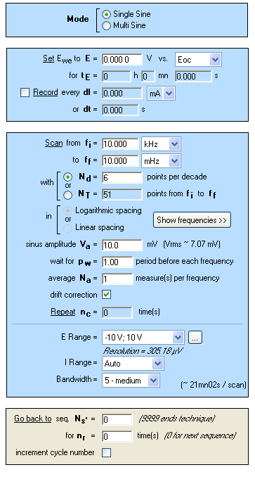
Figure 2: PEIS “Parameters Settings” window.

Figure 3: Nyquist impedance diagram (blue) and ZFit analysis (red) of a LiFePO4 battery with a L1+R1+Q2/R2+Q3 equivalent circuit.

Figure 4: L1+R1+Q2/R2+Q3 equivalent electrical circuit.
In the Equivalent Circuit Edition, the L1+R1+Q2/R2+Q3 circuit has to be defined and added with the Add button, as described in Figure 5. The new circuit is then displayed in blue.

Figure 5: How to add a new electrical equivalent circuit in the ZFit analysis tool.
The results of the ZFit analysis are given in Figure 6. A good agreement is observed between the experimental diagram and the ZFit diagram as shown in Figure 3.
The equivalent circuit used to carry out the fit on the experimental data contains the pattern (R/Q). It is then possible to calculate the pseudo-capacitance. In the ZFit window, select the PseudoC button, and the window given in Figure 7 appears. This means that with the ZFit analysis tool of EC-Lab® and EC-Lab® Express, the calculation of pseudo-capacitance is carried out automatically.
However, the following equivalent circuit L1+R1+Q2/(R2+Q3) (Figure 8) can also be considered to fit the diagram. As shown in Figure 9, the obtained fit (red) is in good agreement with experimental data (blue). The parameters are displayed in the ZFit window given in Figure 10.
However, it is not possible to calculate a pseudo-capacitance value. The pattern in the equivalent circuit is Q/(R+Q) and not the required one (R/Q).

Figure 6: ZFit analysis window obtained with the L1+R1+Q2/R2+Q3 equivalent circuit.

Figure 7: Pseudo-capacitance calculation in the ZFit window obtained with the L1+R1+Q2/R2+Q3 equivalent circuit.

Figure 8: L1+R1+Q2/(R2+Q3) equivalent electrical circuit.

Figure 9: Nyquist impedance diagram (blue) and ZFit analysis (red) of a LiFePO4 battery with a L1+R1+Q2/(R2+Q3) equivalent circuit.

Figure 10: ZFit analysis window obtained with the L1+R1+Q2/(R2+Q3) equivalent circuit.
It is not possible to distinguish between the two fits considering the χ² values, which are very close. Similarly, the values of the fit parameters obtained for the two circuits (Figure 6 and Figure 10) are very close.
Note that in some peculiar cases, it is possible to establish equivalence between the following two electrical circuits L1+R1+Q2/R2+Q3 and L1+R1+Q2/(R2+Q3).
Conclusion
In this note, we have shown how to calculate the pseudo-capacitance of a R/Q circuit, using the ZFit tool EC-lab®. This calculation was performed on data obtained on a LiFePO4 battery. The method to edit and create an equivalent circuit using ZFit was also shown.
Thanks to this method, we can observe the heterogeneity of a material and represent the impedance diagram of the system with a homogeneous surface.
Data files can be found in: C:\Users\xxx-\Documents\EC-Lab\Data\Samples\-Fundamental Electrochemistry\LiFePO4_PEIS_10mHz_12
References
- Handbook of EIS “Electrical circuits containing CPEs”
- E. Barsoukov, J. Ross Mac Donald, Impedance spectroscopy, 2nd Edition, (2005).
Revised in 04/2023


