
What are stopped-flows and how do they help chemists and biochemists understand high-speed chemical reactions?
Latest updated: June 29, 2023Some chemical and biochemical processes take place far too quickly to analyze with standard laboratory equipment, such as bench spectrophotometers. A stopped-flow instrument is a rapid kinetics technique used to follow chemical reactions in the milliseconds to seconds timescale. A stopped-flow can only mix liquids, and the complete stopped-flow system includes a detection instrument.
Stopped-Flows are used across a wide range of academic and industrial applications including drug binding processes and protein stability. Stopped-Flows are key instruments used to increase researchers’ understanding of rapid kinetics and are especially useful for chemists and biochemists.
In stopped-flow experiments, two, three, or four sample solutions are rapidly mixed and injected into an observation cell. When the flow is stopped, the kinetics are recorded with a detector best suited to the chemical properties of the solutions and the information of interest (e.g. particle size, the environment of the fluorophore, chromophore).
| Absorbance | structure of chromophore | MOS-200, MOS-DAD, MOS-500 |
| Fluorescence | environment of fluorophore | MOS-200, MOS-500 |
| 90°light scattering | size of particles | MOS-200, MOS-500 |
| Fluorescence anisotropy | mobility of fluorophore | MOS-200, MOS-500 |
| Circular Dichroism (far UV) | change of secondary structure | MOS-500 |
| Circular Dichroism (aromatic) | tertiary structure | MOS-500 |
| FT-IR/DCS | change of secondary structure | external |
| Conductivity | change of ions concentrations | MCS-200 |
| X-ray | shape and conformation changes | external |
| Neutron scattering | change of structure | external |
The most common detection techniques used in stopped-flow measurements
The history of the stopped-flow
The stopped-flow technique was invented in the 1950s by professor Britton Chance as a result of a need for instrumentation to follow enzymatic reactions in the tens of millisecond time range. In 1983 Yves Dupont from the French research agency, the CNRS (Centre National de la Recherche Scientifique) developed his own stopped-flow for his laboratory for fast fluorescence and radioactive labeling measurements. The design was based on independent stepping motors which were revolutionary compared to existing pneumatic stopped-flow motors. For the first time, stepping motors gave users full control over volume, modularity, and real millisecond performance. BioLogic started to commercialize this stopped-flow and the technical specifications were rapidly improved to match the developing needs of the scientific community. Initially used in enzymology and biology applications, the stopped-flow rapidly found its place in biochemistry, biophysics, and chemistry laboratories, in fact, any lab with a need to follow chemical reactions in the millisecond time scale. BioLogic chose an open design for the stopped-flow so it would not just be a simple mixer and so that it could be used with a large choice of detectors, opening up its use to ongoing research developments. Since 1983, the principle of BioLogic stopped-flow has remained the same, but several generations of instruments have been developed by constantly developing technology to reduce sample consumption, decrease dead time and broaden fields of application. Stopped-flow is mainly used in fundamental research to study binding reactions, protein stability or to understand chemical reaction mechanisms. It is also used in industrial applications to check membrane permeability efficiency or in pharmaceutical research to design new drugs.
The principles of stopped-flow
Single Mixing
In its simplest form, a stopped-flow mixes two solutions. Small volumes of solutions are rapidly and continuously driven into a high-efficiency Ball mixer, so mixing is completed in just a few microseconds. This mixing process then initiates an extremely fast reaction. The newly mixed solution travels to the observation cell and pushes out the contents of the cell (the solution remaining from the previous experiment or from necessary washing steps). The time required for this solution to pass from the mixing point to the observation point is known as dead time. The minimum injection volume will depend on the volume of the mixing cell.
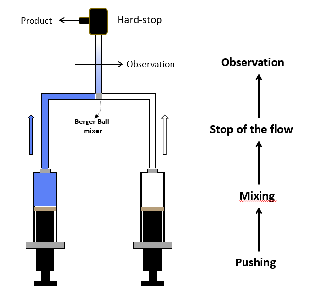
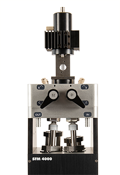
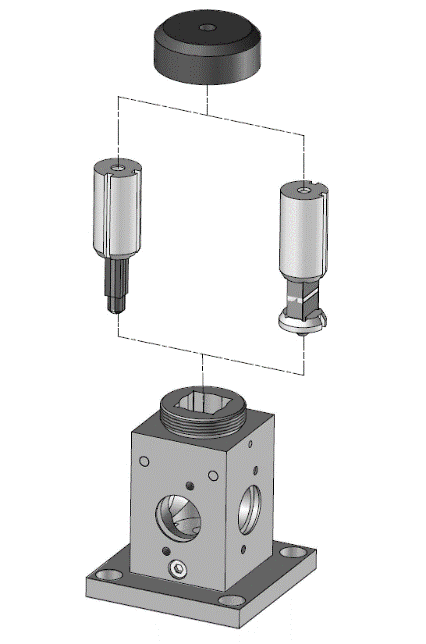
Two syringe stopped-flow
Once enough solution has been injected to completely remove the previous solution, the instrument reaches a stationary state and the flow can be stopped. The flow stop is achieved by synchronizing the stepping motors stop to a stop valve called the hard-stop. Thanks to the hard stop, the flow can be instantaneously stopped so the reaction can be observed without any delay. The stopped-flow also sends a ‘start signal’ to the detector called the trigger so the reaction can be observed. The timing of the trigger is software controlled so the user can trigger at the same time the flow stops or a few milliseconds before the stop to check the stationary state has been reached.
BioLogic stopped-flows are the only instruments produced where each syringe is driven by an individual stepping motor so the volume per shot and the speed of the injection is fully software controlled. The user can therefore inject the same amount of each sample (same mixing ratio) or carry out asymmetric mixing (one volume of one reactant versus a different volume from the second reactant) without manual handling of the driving syringes. The mixing ratio can thus be varied freely within the hardware limitation of the system. This results in a number of clear advantages; namely, an improvement in efficiency, which means that the throughput of samples, which are often very difficult to produce and therefore highly valuable, is optimized, and all wastage minimized. Another clear advantage of such a system is that the process is much easier, and faster, to manage. The ability to program the instrument, with different ratio concentrations, in series, opens up significant experimental possibilities.
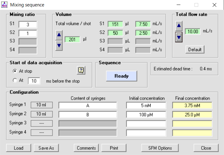
Total software control on mixing ratio, volume delivered and total flow rate.
The rate of a chemical reaction is always associated with temperature. All parts of the stopped-flow (driving syringes, internal lines, mixers, aging lines, cuvette) are temperature-controlled and a probe can be installed on the surface of the cuvette to check the temperature accuracy. In its standard configuration, the temperature can be varied from -20°C to +85°C. For chemical reactions that are too fast to be observed by stopped-flow at these conventional temperatures, options exist to extend the temperature limits to -90°C (cryogenic stopped-flow) so the reaction can be slowed down enough to be observable. A chemical reaction at -90°C is about 1000 times slower than at 20°C so reactions that were in the microseconds time range can be brought to a millisecond time scale. Cryogenic stopped-flow is a powerful technique that can be used in organic chemistry to observe and identify reaction intermediates that could otherwise not be seen at normal temperatures. The temperature limit can also be extended above 85°C for polymerization reactions.
Multi mixing stopped-flow
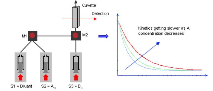
A three syringe-stopped flow has 2 mixers that work consecutively. Syringes 1 and 2 mix first, then the mixture mixes with syringe 3. Two types of experiments can be performed with a multi-mixing stopped-flow.
1/ Concentration dependence studies:
The rate of a chemical reaction is linked to the concentration of the reactants. It is important to know how the rate is affected by concentration changes in order to determine the reaction order and to determine and understand the reaction mechanism. So, to study the influence of the concentration of one reactant, the user usually mixes the same sample with different concentrations of the second sample to see how the kinetics change. Such studies can be performed manually using a two-syringe stopped-flow by manually preparing the different concentrations. But it requires precious time, samples and it is a process that is open to human dilution errors. The benefit of a 3-syringe stopped-flow is to automate this dilution process and to use mixer 1 to change the concentration of the first reactant before mixing with the second. Only the second mixing step is followed optically.
One syringe is therefore loaded with buffer or solvent and is used for the dilution step. For example, a series of shots is made with the following ratio (S1:S2:S3): 0:10:10, 2:8:10, 5:5:10…The ratio (S1+S2):S3 is kept constant so the concentration of S3 is constant while S2 changes at each shot.
3 syringes for concentration dependence studies
A double mixing experiment (also called sequential mixing) is an application where you generate one reactant by mixing two solutions because this reactant is not stable and could therefore not be loaded in a syringe for a single mixing application. So, in this scenario, a first reaction is generated in mixer 1. This mixture is allowed to age, from 2ms to several seconds, in a delay line before being mixed with a third sample. The second reaction is then followed optically. The delay line is also called the aging line, aging loop, or retardation loop but all of these terms refer to the same component. Such experiments are performed to generate an unstable reactant that could not be directly loaded into a two-syringe instrument. The aging time is the time it takes for the solution to pass from mixer 1 to mixer 2. For short aging times (<200ms) the stopped-flow works in continuous flow mode, so the aging time is defined as the ratio of the volume of the delay line divided by the flow rate of solutions through the line. The user can change the delay line itself or can change the flow rate in the software. For longer aging times, the stopped-flow uses an interrupted flow method (push-pause-push) where the flow is stopped between the two mixing events.
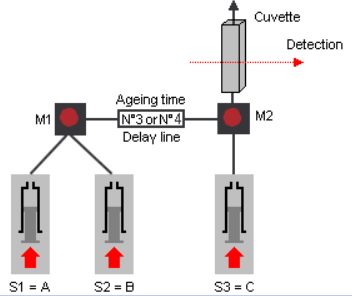
3 syringes are used for double mixing experiments
A four-syringe stopped-flow has three consecutive mixers and four independent motors so it can carry out triple mixing experiments, for example by combining the double mixing and the concentration dependence described above.
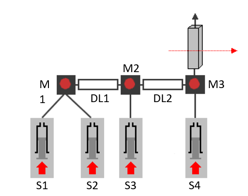
4 syringes, 3 mixers for triple mixing experiments
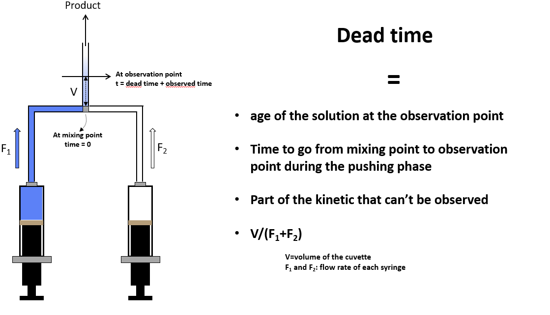
A stopped-flow experiment is always associated with a dead time
The dead time of a stopped-flow instrument is the time it takes for the solution to pass from the center of the mixer, where the reaction starts, to the observation point. This is the part of the reaction you do not see in your stopped-flow recordings. So the lower the dead time, the more you see and the more information you can generate.
Stopped-flow dead time
By definition, the dead time is the cell volume divided by the solution flow rate. In most configurations, the dead time is between 0.5ms and 1 ms. But using the microcuvette accessory you can reach a 200µs dead time. This performance is not only due to the cuvette’s small volume but to the mixing and pushing technology, as the mixing process must be completed much faster than the dead time. Some detection techniques like neutron scattering or FT-IR require larger cells to have sufficient sensitivity so that dead time can be a couple of milliseconds.
Stopped flow and sample consumption
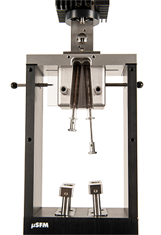
Sample consumption in stopped-flow experiments is paramount. Sample consumption is directly linked to the volume of the observation cuvette, to the performance of the drive mechanism, and to the number of mixing steps you wish to perform, but it can also be linked to the level of modularity you need for your mixing system. BioLogic offers a range of instruments able to fulfill all needs: if micro-volume consumption is the n°1 consideration then a BioLogic µSFM is able to run experiments with a total volume of only 24µl: so this effectively means 12µl of each reactant using 1:1 mixing ratio, but it could go down to 3µl using asymmetric mixing. If small volumes are important but the user needs modularity ( the possibility to carry out multiple mixing or to use the drive mechanism for other techniques like quench flow or freeze quench then a SFM-2000/3000/4000 would be the right choice).
What is the difference between a small volume and microvolume stopped-flow?
A stopped-flow is usually considered to be a microvolume instrument when sample consumption is less than 15µl per experiment, whatever the mixing ratio used. Using a microvolume stopped-flow it should be possible to run a series of experiments with only 100µl in a vial, which also means that the dead volume must be a couple of microliters. To work with such micro volumes the observation cell must have a short light path and a small volume: fluorescence, 90°light scattering, absorbance, and X-ray are the most popular techniques for such microvolume work.
A small volume stopped-flow handles between 50µl-150µl of sample per experiment. It uses larger observation cells and can be used with a large range of detectors (circular dichroism, FT-IR, neutron scattering, etc.). Such instruments are more modular as they can be used or upgraded for double mixing and triple mixing applications.
| Microvolume stopped-flow | Small volume stopped-flow | |
 |  |
|
| Model | µSFM | SFM-2000/3000/4000 |
| Typical volume per shot (1:1) mixing ratio | 12 µl | 50-100 µl |
| Min. volume per shot (asymmetric ratio) | 3 µl | 25µl |
| Modularity | + | +++ |
Stopped-flow: the importance of the observation cell.
The drive mechanism is the same whatever the detection system, but the geometry of the cell can vary to match the detector’s technical requirements (size of beam, sensitivity, access to the beam etc.). Fluorescence is a very sensitive technique so a very small cuvette with a short light path is preferred to minimize the inner sample’s self-absorption (=inner filter effect). A light path from 0.8 mm to 2 mm would be suitable. For absorbance, measurements with a 1 cm light path may be preferred, but the same cuvette can also be used with 1mm light path on its second axis for high absorbing samples.
Different shape of cuvette to match experimental needs; left (fluorescence, CD type cuvette with light path from
0.75 to 2mm),right (TC type cuvette for absorbance, light path 1 cm and 1mm)
For far-UV circular dichroism experiments, 1.5 or 2mm light paths are a good compromise between the size of the signal to be measured and the absorption limitation of the solvents used. Most observation cuvettes are made of high-quality quartz so the stopped-flow can be used from far-UV to NIR region, but CaF2 cells are also available for mid-IR application using FT-IR or dual-comb spectrometers as a detector. The dead time and the sample consumption are directly linked to the size of the observation cell so depending on the cuvette selected, the dead time can be 200µs and sample consumption reduced to 3µl per experiment (using µSFM and asymmetric mixing).
You may be interested in the following articles..
Related products